Debugging method for average light power and extinction ratio parameter of light transmitter

A technology of average optical power and optical transmitter, applied in the direction of electromagnetic wave transmission system, electrical components, transmission system, etc., can solve the problems of production cost reduction, high maintenance and use cost, restriction of production capacity expansion, etc., to reduce production cost , Improve production efficiency and yield, reduce the effect of input

Inactive Publication Date: 2009-07-15
CHENGDU SUPERXON COMM TECH CO LTD
View PDF0 Cites 26 Cited by
  • Summary
  • Abstract
  • Description
  • Claims
  • Application Information

AI Technical Summary

Problems solved by technology

[0008] However, the sampling oscilloscope is expensive, and the cost of maintenance and use is high. It accounts for more than 80% of the construction

Method used


Image

  • Debugging method for average light power and extinction ratio parameter of light transmitter
  • Debugging method for average light power and extinction ratio parameter of light transmitter
  • Debugging method for average light power and extinction ratio parameter of light transmitter

Examples


Embodiment Construction

[0051] The present invention will be further described below in conjunction with the accompanying drawings and embodiments, but the present invention is not limited to the scope of the described embodiments.

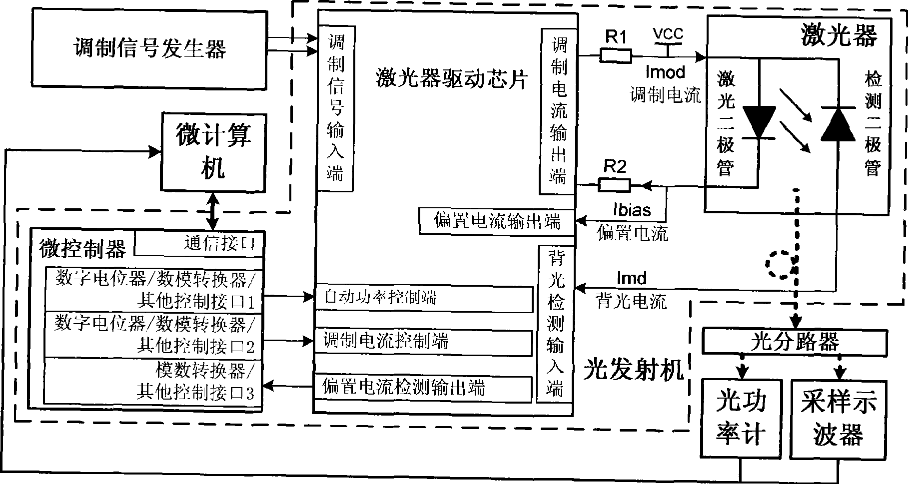
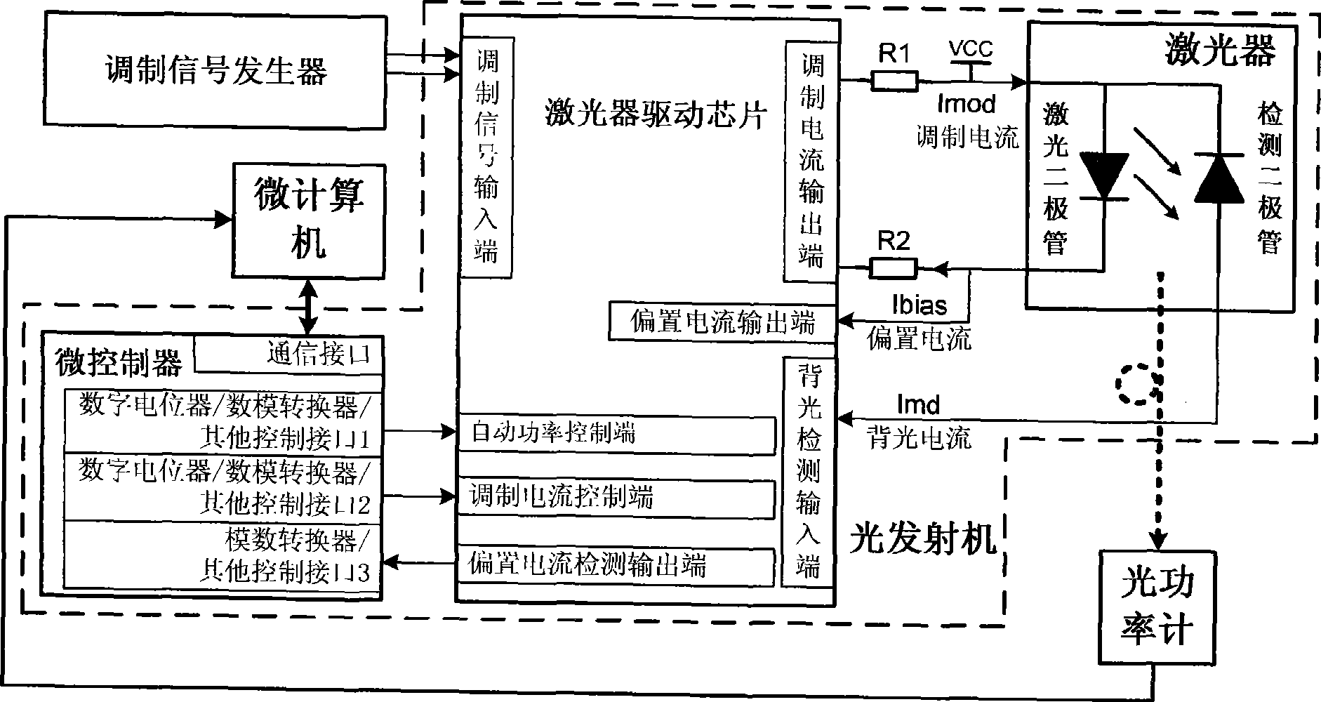
[0052] figure 2 It is a block diagram of the control circuit of the optical power and extinction ratio parameters of the optical transmitter in the specific embodiment of the present invention and a schematic diagram of the debugging platform. like figure 2 As shown, the debugging platform includes a microcomputer, a modulation signal generator, an optical power meter and an optical transmitter. The optical transmitter to be debugged takes the GEPON ONU optical transmission module as an example. The IEEE802.3ah-2000 standard stipulates that the extinction ratio of the optical transmitter should be greater than 6dB, and the optical power should be -1dBm ~ 4dBm. The laser model can be ML720AA46S-01 from MITSUBISHI Company. The typical value range of the threshold current...


PUM


Abstract

The present invention discloses a method for debugging the average optical power and extinction ratio parameter of optical transmitter. The optical transmitter is set to an automatic power control mode. The modulation signal coupling mode of the laser driving chip of light transmitter and the laser is set to a direct-current coupling mode. A microcomputer tests the luminous efficiency and threshold current of laser of the optical transmitter. The microcomputer debugs the average optical power of optical transmitter to a preset average optical power area. The microcomputer debugs the present extinction ratio of optical transmitter to a preset extinction range. The technical scheme according to the invention can greatly reduce the investment of product line on the device and has the advantages of automatic debugging realization, reduced production cost and increased production efficiency.

Description

technical field [0001] The invention relates to the technical field of optical transmitters, in particular to a method for debugging average optical power and extinction ratio parameters of an optical transmitter. Background technique [0002] In the production process of the optical transmitter, due to the poor consistency of the characteristics of active devices such as lasers, some parameters in the laser control circuit must be adjusted in order to achieve the consistency of the final parameters of the optical transmitter. The more important debugging parameters are the average optical power Pavg of the optical transmitter and the extinction ratio ER parameters. In the existing debugging method, the measuring instrument of the average optical power Pavg parameter is an optical power meter, and the measuring instrument of the extinction ratio ER parameter is a sampling oscilloscope, such as figure 1 shown. [0003] In the process of digital signal communication transmis...

Claims


Application Information

Patent Timeline
IPC IPC(8): H04B10/145H04B10/155H04B10/564
Inventor 张银宝余涛周庭铭蒋小青
Owner CHENGDU SUPERXON COMM TECH CO LTD
Why Eureka
Try Eureka