Off-course driving device of wind-driven generator

A technology of yaw driving device and wind power generator, which is applied in the control of wind power generators, wind power generators, wind power generation, etc. It can solve the problems of complex reliability of the driving mechanism, large resistance of yaw driving, and reduced reliability, etc., so as to avoid Effects of broken pipes, improved power generation efficiency, and increased reliability

Inactive Publication Date: 2009-07-22
HARBIN INST OF TECH
View PDF0 Cites 10 Cited by
  • Summary
  • Abstract
  • Description
  • Claims
  • Application Information

AI Technical Summary

Problems solved by technology

[0007] The present invention aims at the defects of complex driving mechanism and low reliability of the yaw driving device of the existing wind power generator, the reduced reliability of the braking of the yaw braking device, the large resistance of the yaw driving and the high cost, and proposes a Yaw drives for wind turbines

Method used


Image

  • Off-course driving device of wind-driven generator
  • Off-course driving device of wind-driven generator
  • Off-course driving device of wind-driven generator

Examples


specific Embodiment approach 1

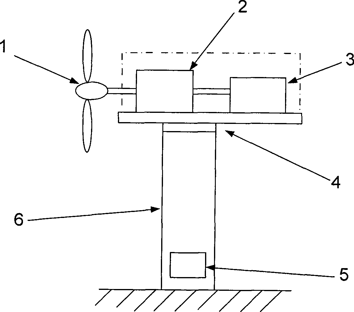
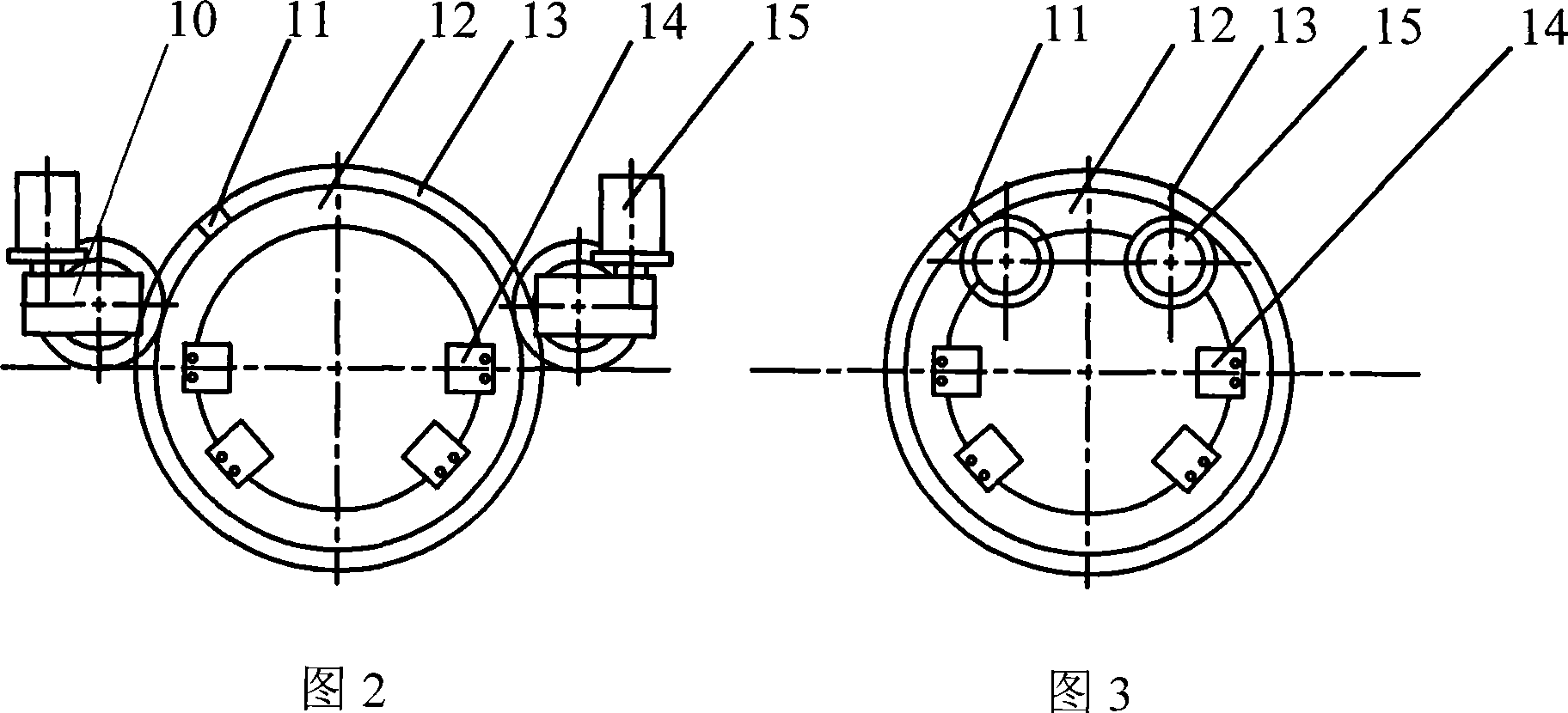
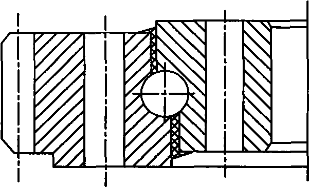
[0013] Specific implementation mode one: combine Figure 6 To illustrate this embodiment, the yaw driving device of the wind power generator is composed of a wind vane, a direct-drive electro-hydraulic servo low-speed high-torque hydraulic motor, a yaw chainring 13, and a yaw braking device; the wind vane sends an electric signal to change the wind direction In the processor of the control system, after comparison, the processor sends a clockwise or counterclockwise yaw command to the direct-drive electro-hydraulic servo low-speed high-torque hydraulic motor, and the output shaft of the direct-drive electro-hydraulic servo low-speed high-torque hydraulic motor The installed drive gear meshes directly with the yaw chainring 13; the locking part of the yaw braking device is directly installed on the output shaft of the direct-drive electro-hydraulic servo low-speed high-torque hydraulic motor, and the direct-drive electro-hydraulic servo low-speed high-torque hydraulic motor The...

specific Embodiment approach 2

[0014] Specific implementation mode two: combination Figure 6Describe this embodiment, the difference between this embodiment and the specific embodiment is that the yaw braking device is composed of a proportional relief valve 31, a hydraulic source 32 and a yaw brake 33; the oil inlet of the proportional relief valve 31 and the hydraulic source The oil outlet of 32 is connected to the control oil port of yaw brake 33, the oil outlet of proportional relief valve 31 and the oil inlet of hydraulic source 32 are respectively connected to two oil tanks; yaw brake 33 is mechanically locked Clutch; the locking part of the yaw brake 33 is directly installed on the 26 shafts of the low-speed high-torque hydraulic motor, and yaw braking and yaw damping are realized by tightening and loosening the 26 shafts of the low-speed high-torque hydraulic motor. The yaw brake 33 has a hydraulic source independent of the yaw drive motor, which can ensure that the brake can act independently of t...

specific Embodiment approach 3

[0015] Specific implementation mode three: combination Figure 6 Describe this embodiment, the difference between this embodiment and the specific embodiment 1 or 2 is that the oil supply valve 24 is composed of two hydraulic control check valves, and the two hydraulic control check valves are respectively the first hydraulic control check valve and the second hydraulic control check valve. Two hydraulic control check valves; one oil port and the control oil port of the first hydraulic control check valve are respectively connected with two oil passages between the two-way quantitative pump 23 and the low-speed high-torque hydraulic motor 26, and the second hydraulic control check valve One oil port of the valve is connected to the oil passage connected to the control oil port of the first hydraulic control check valve, and the control oil port of the second hydraulic control check valve is connected to an oil port of the first hydraulic control check valve. The connected oil ...


PUM


Abstract

The invention discloses a yaw driving device of a wind driven generator, relates to the technical field of wind power generating equipment, and solves the defects of complex driving mechanism and low reliability of the existing yaw driving devices of wind driven generators, reduced braking reliability of yaw braking devices, big yaw driving resistance and high cost. A driving gear arranged on a direct drive electrohydraulic servo low-speed and large-torque hydraulic motor output shaft is directly engaged with a yaw fluted disc; a locking part of a yaw braking device is directly arranged on the direct drive electrohydraulic servo low-speed and high-torque hydraulic motor output shaft; a variable-frequency motor of the direct drive electrohydraulic servo low-speed and high-torque hydraulic motor is connected with a two-way constant displacement pump, the two-way constant displacement pump is connected with the low-speed and large-torque hydraulic motor by a hydraulic lock, and an oil feeding valve is connected to two oil channels between the two-way constant displacement pump and the low-speed and large-torque hydraulic motor. The yaw driving device has the advantages of good reliability, simple structure, low cost, stepless regulation of yawing velocity and the like.

Description

technical field [0001] The invention relates to the technical field of wind power generation equipment, in particular to a wind power generator driving device. Background technique [0002] Wind energy is the conversion form of solar energy. It is a renewable natural energy that does not produce any pollutant emissions. It is the most promising green energy in the 21st century and one of the most important new power sources for the sustainable development of human society and economy. one. [0003] At present, commercial large-scale wind turbines are generally horizontal axis wind turbines, which include wind rotor 1, transmission system 2, generator 3, yaw drive device 4, control system 5 and tower 6, such as figure 1 shown. The function of the wind wheel is to convert wind energy into mechanical energy. It consists of blades with excellent aerodynamic performance (currently commercial units generally have 2 to 3 blades) mounted on the hub. Acceleration, transfer power t...

Claims


Application Information

Patent Timeline
Patent Type & Authority Applications(China)
IPC IPC(8): F03D7/02
CPCY02E10/723Y02E10/72
Inventor 苏文海姜继海刘庆和马琛俊
Owner HARBIN INST OF TECH
Why Eureka
Try Eureka