Discharge lamp with an auxiliary ignition element

A technology for auxiliary components and discharge lamps, applied in discharge lamps, gas discharge lamps, high-pressure discharge lamps, etc., can solve problems such as safety risks and devitrification of discharge vessels, and achieve the effect of preventing electrolysis and improving starting characteristics.

Inactive Publication Date: 2009-07-22
OSRAM GMBH
View PDF1 Cites 2 Cited by
  • Summary
  • Abstract
  • Description
  • Claims
  • Application Information

AI Technical Summary

Problems solved by technology

A disadvantage of this high-pressure discharge lamp is that, on the one hand, it is not suitable for an embodiment without an outer bulb, since the auxiliary ignition wire protrudes from the discharge lamp at an acute angle in the operating state of the discharge lamp, so that undesirable The ground contacts the luminous means and on the other hand requires additional installation and cost outlays in order to install and align the thermal bimetallic strip with the auxiliary ignition wire on the discharge vessel
In such lamps, at the operating temperature of the discharge lamp, devitrification of the discharge vessel (crystallization of the glass) occurs due to the ignition auxiliary wire on the discharge vessel made of glass and thus leads to a safety risk

Method used


Image

  • Discharge lamp with an auxiliary ignition element

Examples


Embodiment Construction

[0014] Refer to the following The invention is explained in the context of high-pressure discharge lamps, which are used, for example, in microscopy or in plastics technology. However, the discharge lamp according to the invention is by no means limited to such a discharge lamp.

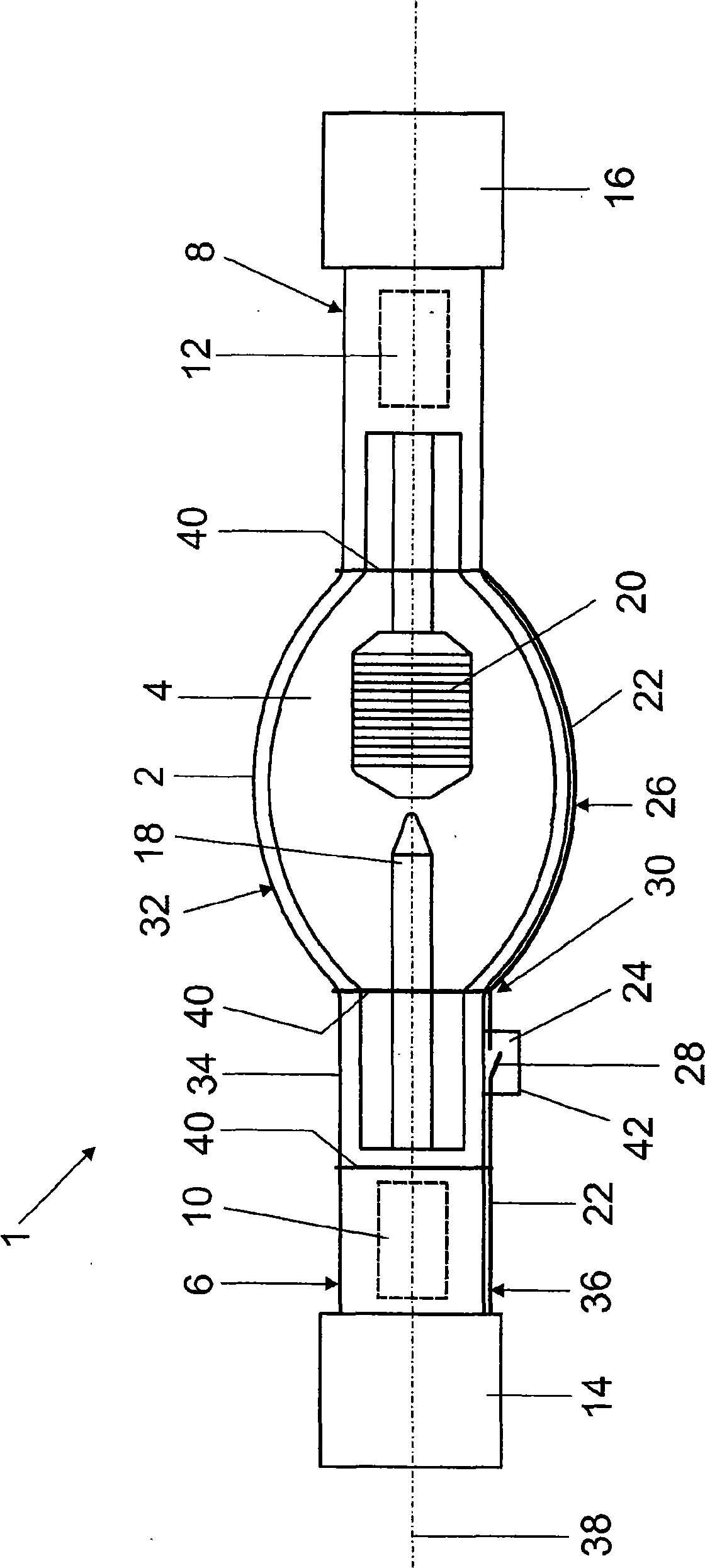
[0015] The only figure shows the use of short arc technology to form the lamp cap on both sides Schematic view of a high-pressure discharge lamp 1 . The discharge lamp has a discharge vessel 2 made of quartz glass with an inner space 4 and two diametrically opposed sealed base necks 6 , 8 each having a schematically indicated molybdenum film The not-shown power supply of the seals 10 , 12 is also provided with cap sockets 14 , 16 . Two diametrically opposed electrodes 18 , 20 protrude into interior space 4 , which electrodes are each connected to one of the power supply devices and between which a gas discharge is formed during lamp operation. For this purpose, an ionizable filling is contained...


PUM


Abstract

Disclosed is a discharge lamp, in particular a high pressure discharge lamp, with at least one discharge vessel and at least one ignition assisting element, preferably an ignition assisting wire or an electrically conducting coating of the discharge vessel, which element can be electrically connected to a power feed to the discharge lamp and which extends at least in some sections along the discharge vessel, wherein a device is provided for interrupting the electrical connection between at least one partial section of the ignition assisting element and the power feed in the operating state of the discharge lamp. Additionally disclosed are an ignition assisting device and a method for operating a discharge lamp of this kind.

Description

technical field [0001] The invention relates to a discharge lamp, in particular a high-pressure discharge lamp, having at least one discharge vessel and at least one ignition aid, in particular an ignition aid wire or an electrically conductive coating of the discharge vessel, which can It is electrically conductively connected to a power supply of a discharge lamp and extends at least in sections along the discharge vessel, and the invention also relates to a method for operating such a discharge lamp. Furthermore, the invention relates to an ignition aid for such a discharge lamp. Background technique [0002] Such a discharge lamp is known, for example, from DE 90 04 811 U1 of the applicant. These conventional discharge lamps, which are designed as sodium high-pressure discharge lamps, have a discharge vessel made of aluminum oxide ceramic, which has an inner space into which two diametrically opposed electrodes protrude, between which electrodes the lamp operates The d...

Claims


Application Information

Patent Timeline
Patent Type & Authority Applications(China)
IPC IPC(8): H01J61/54H01J61/56
CPCH01J61/547H01J61/56H01J61/544H01J61/073H01J61/84H01J61/30
Inventor 马蒂亚斯·莫克尔
Owner OSRAM GMBH
Why Eureka
Try Eureka