Automatic revolving table for robot teeming line

An automatic rotary and pouring line technology, which is applied in the direction of manufacturing tools, metal processing equipment, casting molten material containers, etc., can solve the problems of small load, unguaranteed, inability to meet the accuracy of pouring mold shell placement and positioning, and save time , save manufacturing cost, increase the effect of carrying capacity

Active Publication Date: 2009-07-29
鹰普(中国)有限公司
View PDF0 Cites 2 Cited by
  • Summary
  • Abstract
  • Description
  • Claims
  • Application Information

AI Technical Summary

Problems solved by technology

[0002] In the existing technology, most of the rotary tables are standard type, with small load capacity, and the structure cannot meet the accuracy of the

Method used


Image

  • Automatic revolving table for robot teeming line
  • Automatic revolving table for robot teeming line
  • Automatic revolving table for robot teeming line

Examples


Embodiment Construction

[0018] Below the present invention will be further described in conjunction with the embodiment in the accompanying drawing:

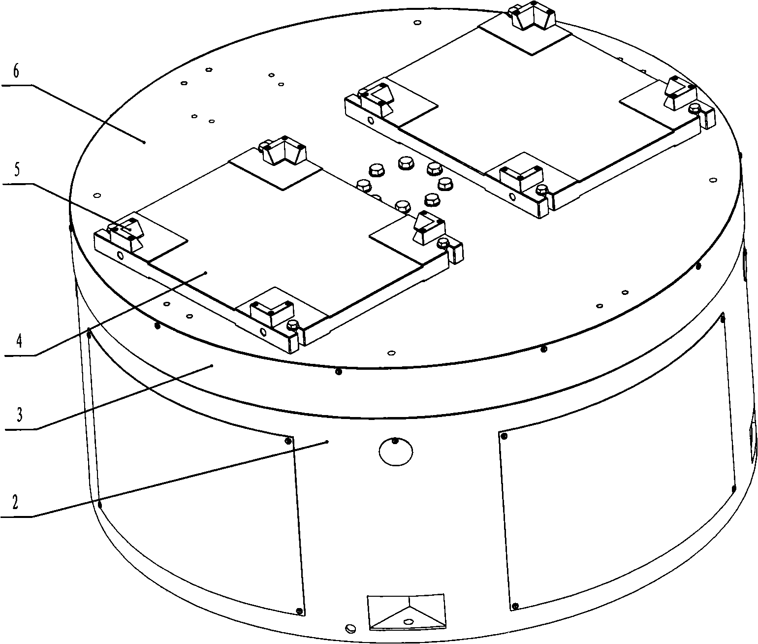
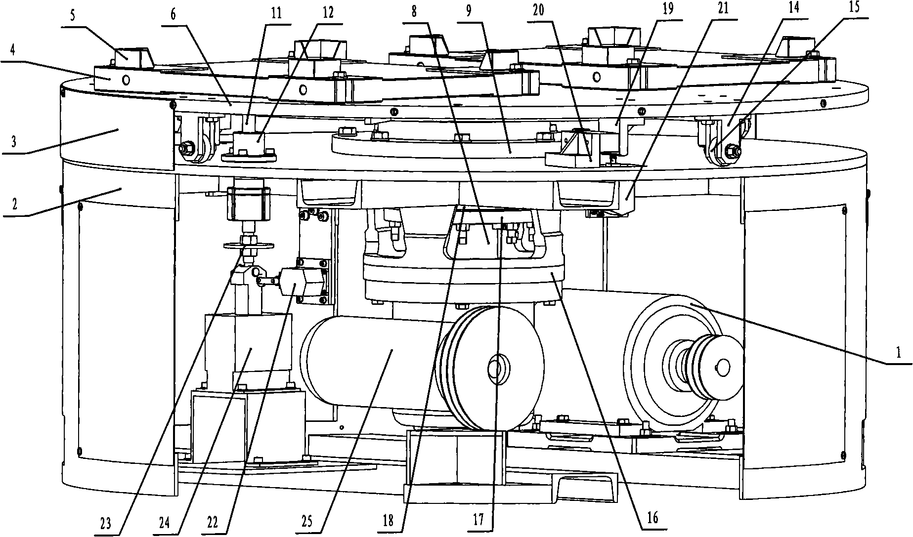
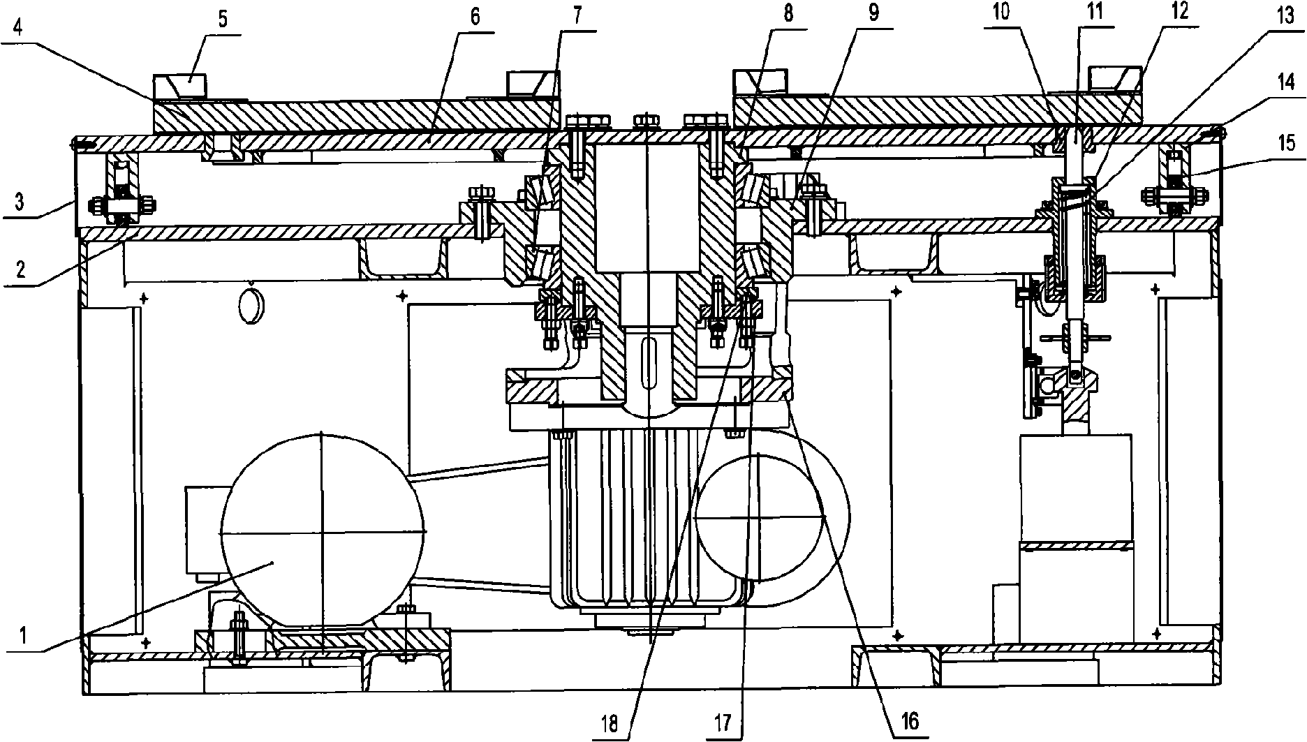
[0019] Figure 1 ~ Figure 4 As shown, it includes motor 1, base 2, platform outer shield 3, box positioning base 4, box positioning block 5, rotary table turning surface 6, tapered roller bearing 7, main rotary shaft 8, bearing seat 9, positioning Guide sleeve 10, positioning guide rod 11, positioning guide rod seat 12, spring 13, auxiliary support 14, auxiliary support roller 15, reducer connecting flange 16, bearing gland 17, bearing pressure plate 18, iron stopper 19, buffer Block support 20, plunger roller type travel switch 21, single-wheel travel switch 22, single-wheel travel switch strike plate 23, traction electromagnet 24, worm gear reducer 25.

[0020] In the present invention, the motor 1 is connected to the base 2 through the motor bottom plate; the bearing seat 9 is connected to the base 2, fastened with screws, and guaranteed to be coax...


PUM


Abstract

The invention relates to an automatic revolving table structure for a robot casting line, which comprises a motor, a pedestal, a main revolving shaft, a worm and gear speed reducer, a revolving table revolution surface and an outer table cover. The automatic revolving table structure for the robot casting line is characterized in that the motor and the worm and gear speed reducer are connected with each other through gearing down by a V-type belt; a tractive electromagnet is connected with the pedestal through a tractive electromagnet pedestal; a buffer block support is arranged on the revolving table revolution surface; a buffer block is arranged on the buffer block support; a positioning guide sleeve is sleeved on a positioning guide rod which is arranged inside the pedestal through a positioning guide rod seat; a spring is arranged inside the positioning guide rod seat; an auxiliary support is arranged under the revolving table revolution surface; an auxiliary support roller is arranged inside the auxiliary support; and a box body positioning pedestal is symmetrically arranged on the revolving table revolution surface. The automatic revolving table structure for the robot casting line not only can guarantee the accuracy of placement and positioning of a manipulator clamping position and a casting die shell but also can guarantee the improvement of the production efficiency during operation and the capability of improving the safety factor of operations.

Description

technical field [0001] The invention relates to an automatic rotary workbench structure for a robot pouring line. Specifically, the automatic rotary workbench is the placement and positioning of the clamping part of the robot hand and the casting mold shell before the robot pours, and belongs to the technical field of large-scale rotary workbenches. Background technique [0002] In the prior art, most of the rotary tables are standard type with small load capacity, and the structure cannot satisfy the accuracy of placement and positioning of the clamping part of the robot hand and the pouring mold shell during robot pouring, and cannot guarantee safety and efficiency. Contents of the invention [0003] The purpose of the present invention is to overcome the above disadvantages, thereby providing an automatic rotary workbench structure for a robot pouring line, which can not only ensure the accuracy of the placement and positioning of the clamping part of the robot hand and ...

Claims


Application Information

Patent Timeline
IPC IPC(8): B22D41/13
Inventor 朱国宏
Owner 鹰普(中国)有限公司
Why Eureka
Try Eureka