In-orbit monitoring method for 6 freedom change between space three-linear array CCD camera lens

A degree of freedom, three-line array technology, applied in the field of aerospace satellite photogrammetry, can solve problems such as complicated process, inability to perform real-time monitoring, and long time consumption

Inactive Publication Date: 2009-08-05
BEIJING RES INST OF SPATIAL MECHANICAL & ELECTRICAL TECH +1
View PDF0 Cites 22 Cited by
  • Summary
  • Abstract
  • Description
  • Claims
  • Application Information

AI Technical Summary

Problems solved by technology

However, this method is very complicated and takes a long time. It is suitable for regular inspection of the accuracy of the angle between the ca...

Method used


Image

  • In-orbit monitoring method for 6 freedom change between space three-linear array CCD camera lens
  • In-orbit monitoring method for 6 freedom change between space three-linear array CCD camera lens
  • In-orbit monitoring method for 6 freedom change between space three-linear array CCD camera lens

Examples


Embodiment Construction

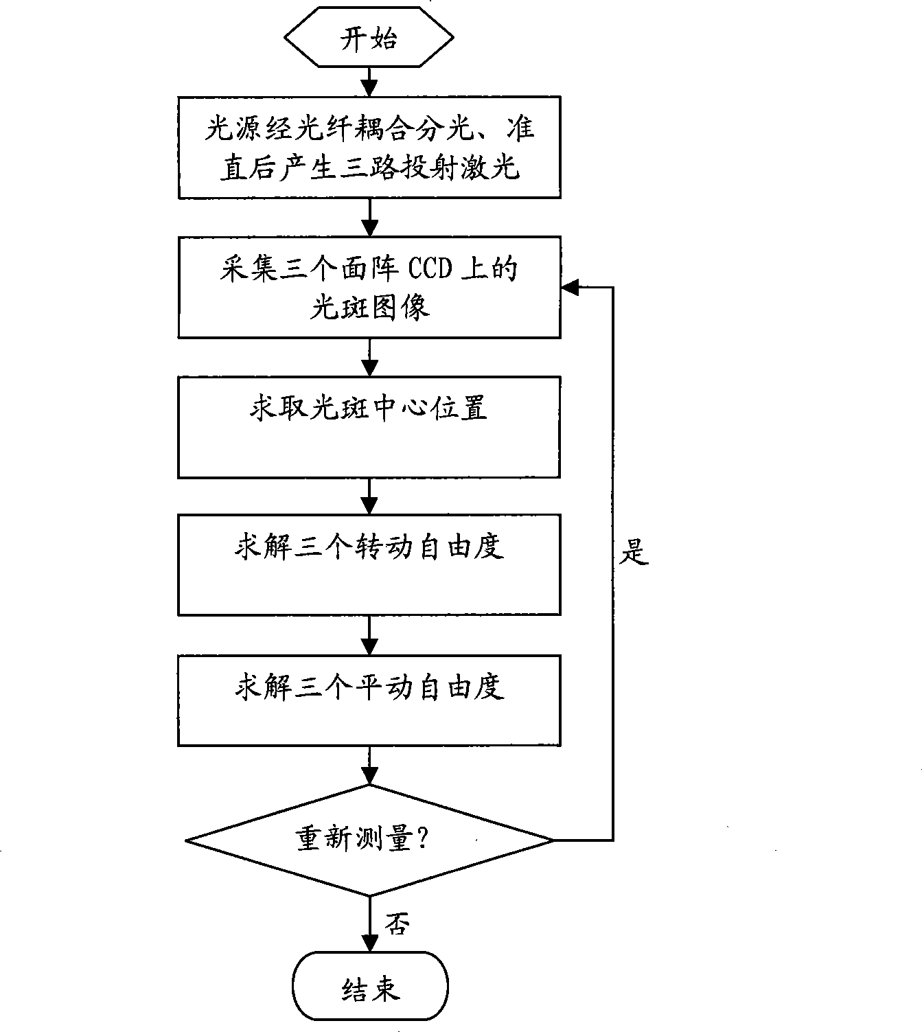
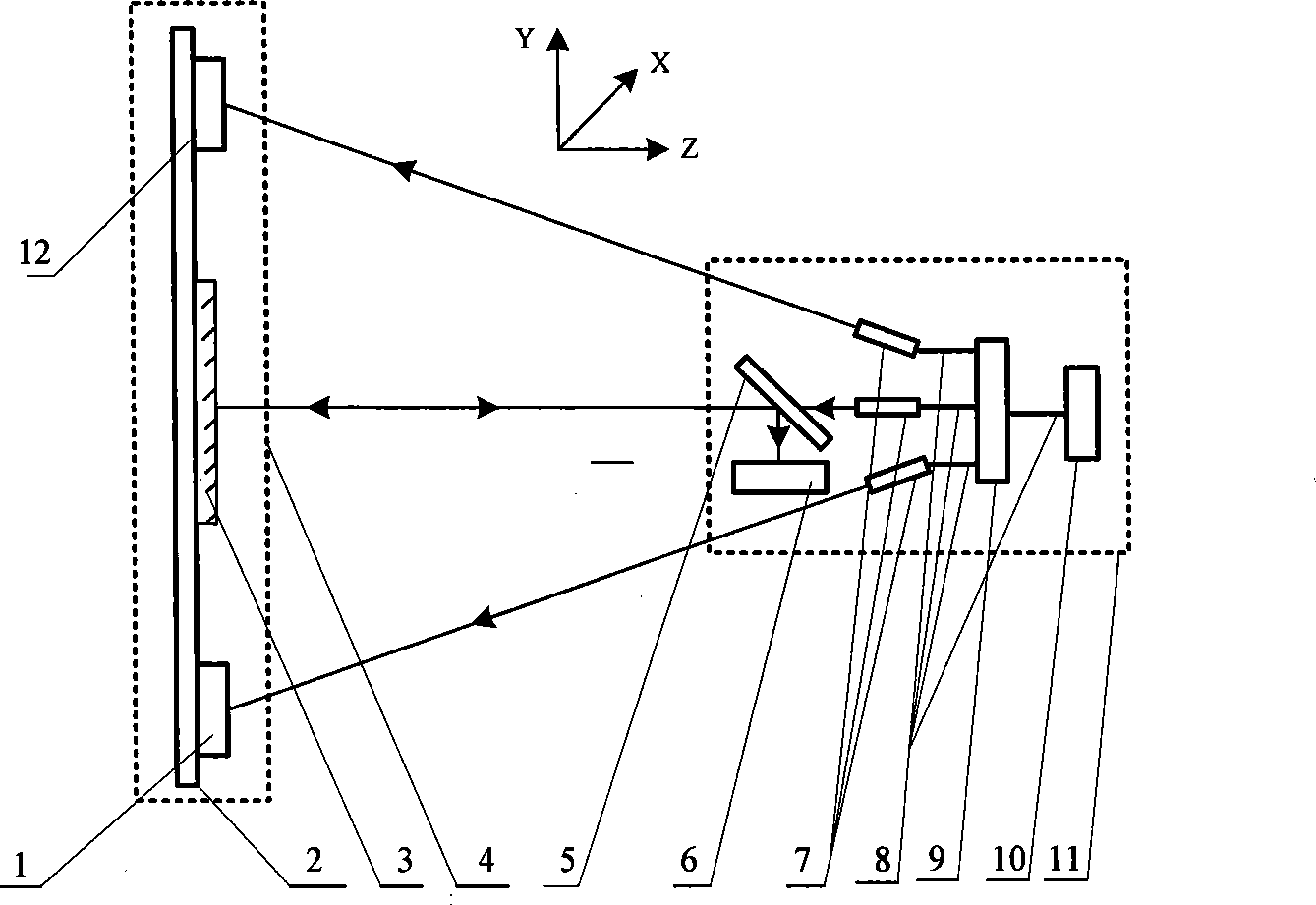
[0029] Such as figure 1 , 2 Shown is a flow chart and a schematic diagram of the monitoring method of the present invention. figure 2 Middle: 4 and 11 represent camera lens B and camera lens A respectively, 2 is the measurement bracket, the measurement bracket is located on the camera lens B, and is used to rigidly fix the laser reflection receiving device. The laser reflection receiving device includes a plane mirror 3, a second surface Array CCD12 and the third array CCD1. The laser emitting and receiving device is located on the camera lens A, and the laser emitting and receiving device includes a semiconductor laser light source 10 (other laser light sources can also be selected), a fiber coupler 9, a half-mirror 5 and the first area array CCD6, and the 9 is an optical fiber coupling 7 is a collimator (three), used to collimate the three lasers, and 8 is an optical fiber (four).

[0030] Since the measurement bracket is rigidly fixed with a lens B to be tested of the a...


PUM


Abstract

The invention relates to an on-line monitoring method of the change of six freedom degrees between the lenses of an astronautical CCD camera with three linear arrays. A laser emitting and receiving device which comprises a laser source, an optical fibre coupler, a laser aligner, a semi-transparent semi-reflecting mirror and a first area array CCD camera is rigidly fixed on a camera lens A, and a laser reflecting and receiving device which comprises a plane mirror, a second area array CCD camera and a third area array CCD camera is rigidly fixed on the a camera lens B. The optical fibre coupler divides lasers emitted from the laser source into three paths, and then, the lasers are respectively aligned by the laser aligner and are output, wherein two paths of the lasers are respectively and directly projected on the two area array CCD cameras of the laser reflecting and receiving device, and the other path of the lasers are reflected on the single area array CCD camera of the laser emitting and receiving device. The change of three rotating freedom degrees and three translational freedom degrees between the lenses of the astronautical camera is solved through the change of facula positions on each area array CCD camera. In the invention, a non-contact measurement method is adopted, the structure of the astronautical camera can not be changed, the processes of installation and adjustment are convenient, the structure is compact, and the on-line operation mode can be achieved.

Description

technical field [0001] The invention belongs to the technical field of aerospace satellite photogrammetry, and relates to a method for on-orbit monitoring of 6-degree-of-freedom changes between lenses of aerospace three-line array CCD cameras. Background technique [0002] The relative positional relationship between the lenses of the aerospace three-line array CCD camera is an important parameter. The relative 6 degrees of freedom change between lenses includes 3 translational degrees of freedom and 3 rotational degrees of freedom, which need to be measured separately. At present, the relative positional relationship between the three-line-array CCD camera lenses in the aerospace industry can only be determined by precise verification in the ground laboratory before the satellite is launched. This leads to changes in the relative positional relationship between the lenses of the aerospace three-line array CCD camera, which leads to changes in the azimuth elements in the ca...

Claims


Application Information

Patent Timeline
IPC IPC(8): G01C25/00G01C11/02
Inventor 吕勇高卫军吕乃光周小华孙鹏孙世君
Owner BEIJING RES INST OF SPATIAL MECHANICAL & ELECTRICAL TECH
Why Eureka
Try Eureka