Permanent magnetic push-pull brushless motor
A brushless motor, permanent magnet technology, applied in electromechanical devices, electrical components, electric components, etc., can solve problems such as low overload capacity and efficiency, low power density and efficiency, and difficult maintenance.
- Summary
- Abstract
- Description
- Claims
- Application Information
AI Technical Summary
Problems solved by technology
Method used
Image
Examples
Embodiment 1
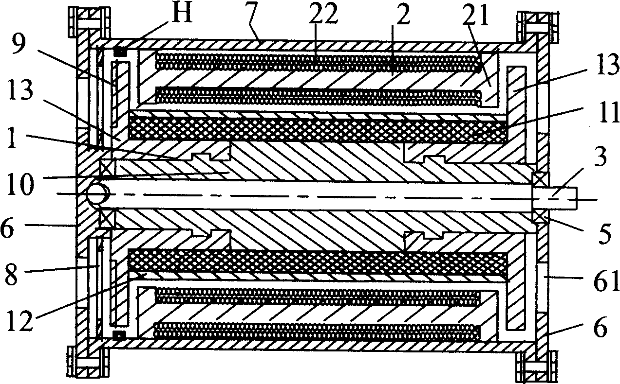
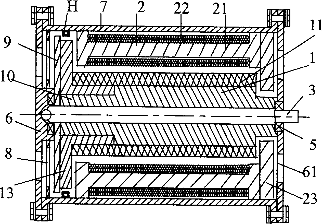
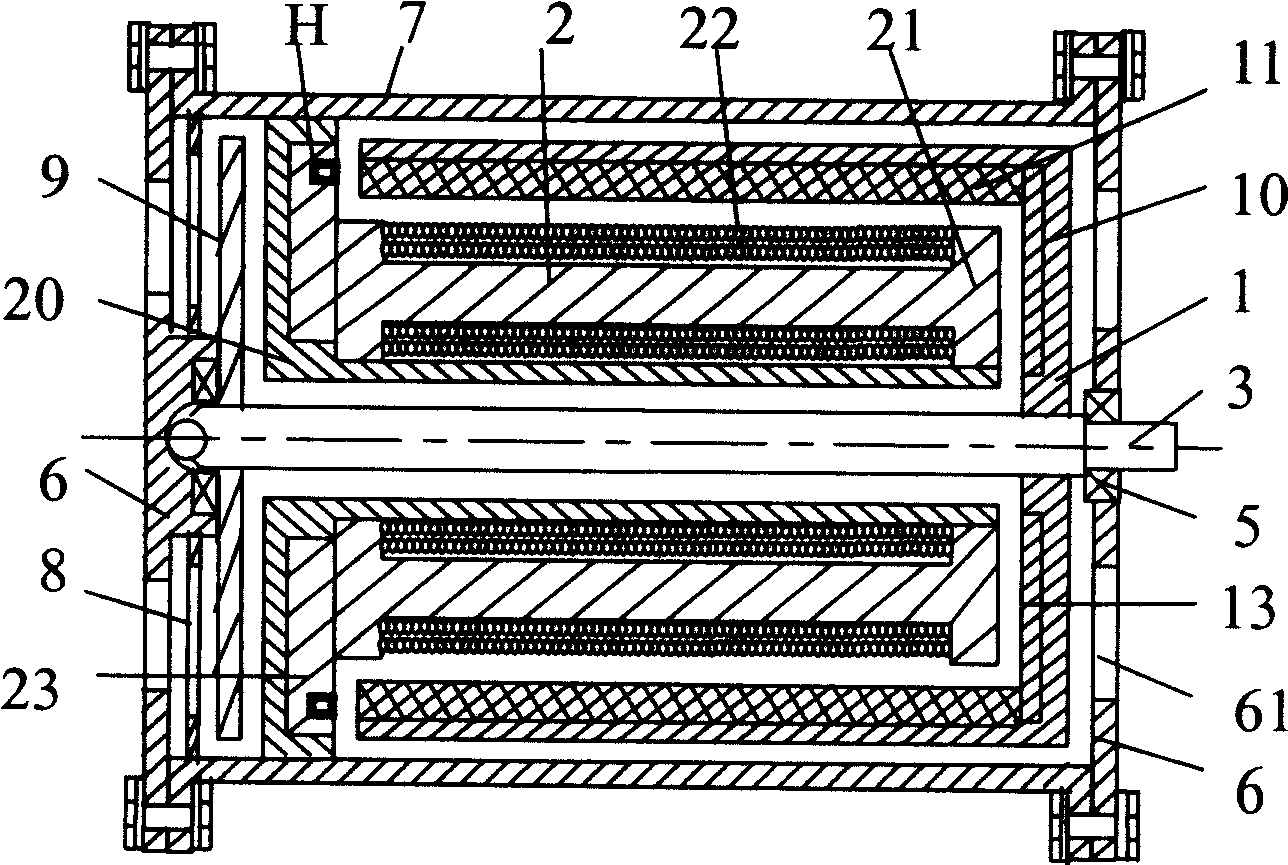
[0052] Embodiment 1: As shown in Figure 11b1, it is "two pairs" 'Shaped axially magnetized rotor with two pairs of permanent magnets' 'Shaped commutation stator axial magnetic pole' motor adopts the "single-phase to two-phase DC commutation circuit" shown in Figure 13a1, and the signal control circuit is collected by two sensors (unipolar or bipolar). When the motor is not started, since the stator coil core is attracted by the permanent magnet of the rotor, one of the sensors H1 and H2 is always turned to align with the magnetic pole of the rotor S. Therefore, as shown in Figure 11b1 and Figure 13a1, when the sensor H2 senses When the rotor magnetic pole is S2, a positive signal is output, VT3 and VT4 are turned on, B winding is energized, the stator magnetic poles BN1, BN2 are repelled by the rotor magnetic poles N1, N2, and the stator magnetic poles BS①, BS② are respectively repelled by the rotor magnetic poles S②, S①, almost at the same time BS① and BS② attract N② and N...
Embodiment 2
[0053] Embodiment 2: As shown in Figure 11b4, it is "two pairs" 'Shaped rotor permanent magnet configuration two pairs' ’-shaped commutated stator radial pole” motor, the end of the stator coil close to the casing adopts “ "shaped yoke, which extends the magnetic circuit axially, and the same end of the corresponding rotor adopts a fan-shaped yoke, which extends the yoke radially. The motor adopts the "single-phase to two-phase DC commutation circuit" shown in Figure 13a3 ", use a bipolar sensor to control the circuit, the switch is a pair of NPN and PNP transistors. When H senses the rotor magnetic pole S1, it outputs a positive signal, VT1 is turned on, the stator A winding is energized, and the rotor rotates 90° to the right; When H senses the rotor magnetic pole N2, it outputs a negative signal, then VT1 is cut off, and at the same time, VT2 is turned on because of the negative electric signal induced by the control pole, the stator B winding is energized, and the roto...
Embodiment 3
[0054] Embodiment three: As shown in Figure 11c1, it is "two pairs" 'Shaped rotor with three pairs of permanent magnets' The motor with 'shaped commutation stator radial magnetic pole' adopts the "single-phase to three-phase DC commutation circuit" shown in Figure 13a6, and uses three unipolar sensors to control the circuit. See the figure, the sensor H2 senses the rotor magnetic pole At S2, a positive signal is output, VT3 and VT4 are turned on, the B winding is energized, and the rotor rotates 60° to the right; then, the sensor H2 cannot sense the rotor magnetic pole, the output signal stops, VT3 and VT4 are cut off, the B winding is powered off, and the sensor H3 senses the rotor magnetic pole S2, outputs a positive signal, VT5 and VT6 are turned on, the C winding is energized, and the rotor rotates 60° to the right; then the sensor H3 cannot sense the rotor magnetic pole, the output signal stops, VT5 and VT6 are cut off, and the C winding Power off, at the same time the...
PUM
 Abstract
Description
Claims
Application Information
 - R&D
- Intellectual Property
- Life Sciences
- Materials
- Tech Scout
- Unparalleled Data Quality
- Higher Quality Content
- 60% Fewer Hallucinations
Browse by: Latest US Patents, China's latest patents, Technical Efficacy Thesaurus, Application Domain, Technology Topic, Popular Technical Reports.
© 2025 PatSnap. All rights reserved.Legal|Privacy policy|Modern Slavery Act Transparency Statement|Sitemap|About US| Contact US: help@patsnap.com


