Noncircular gear drive system transplanting mechanism capable of eliminating pitch play

A non-circular gear and backlash elimination technology, applied in the field of agricultural machinery, can solve the problems of vibration of the planting arm, no elimination of backlash, affecting the uniformity of the amount of seedlings taken and the quality of transplanting, and achieves good erection of the seedlings, gears The effect of large modulus and adjustable backlash

Inactive Publication Date: 2009-08-12
ZHEJIANG SCI-TECH UNIV
View PDF0 Cites 7 Cited by
  • Summary
  • Abstract
  • Description
  • Claims
  • Application Information

AI Technical Summary

Problems solved by technology

[0003] There is no tooth backlash in the non-circular gear transmission mechanism from a theoretical point of view, but in practical applications, due to machining and assembly errors, as well as wear in use, the meshing backlash of non-circular gears will occur, causing the planting arm to vibrate during work , thus affecting the uniformity of the amount of seedlings taken and the quality of transplanted rice seedlings
In the existing non-circular gear transmission system, there is no device for eliminating backlash

Method used


Image

  • Noncircular gear drive system transplanting mechanism capable of eliminating pitch play
  • Noncircular gear drive system transplanting mechanism capable of eliminating pitch play
  • Noncircular gear drive system transplanting mechanism capable of eliminating pitch play

Examples


Embodiment Construction

[0019] The present invention will be further described below in conjunction with drawings and embodiments.

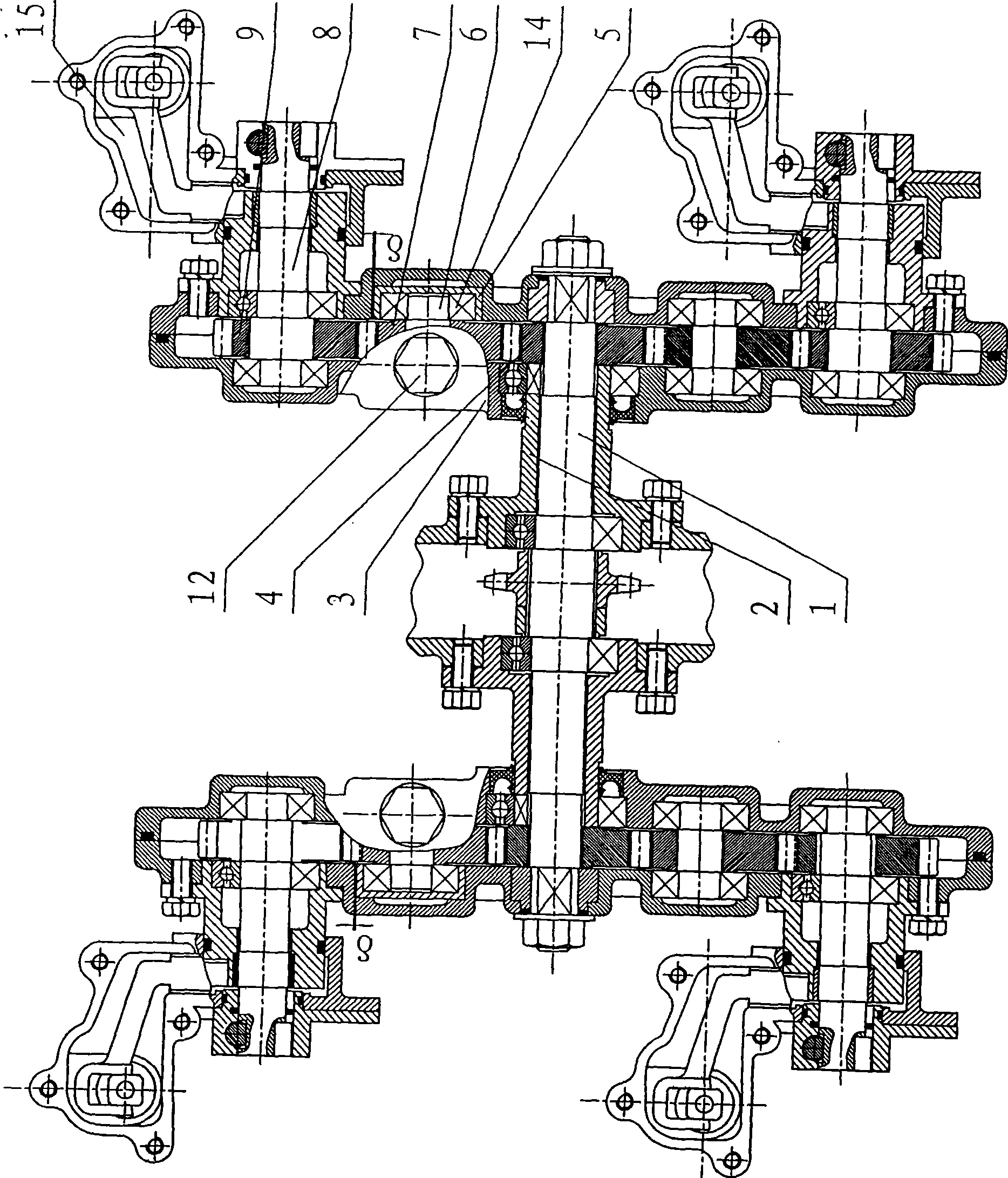
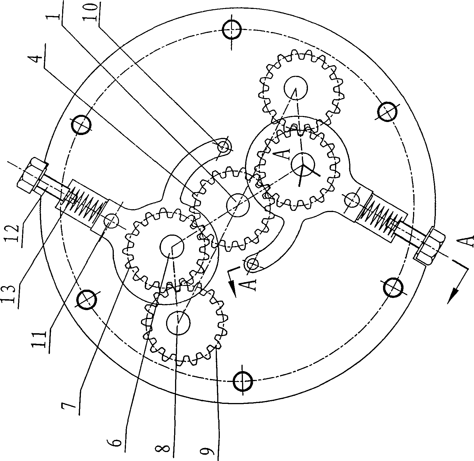
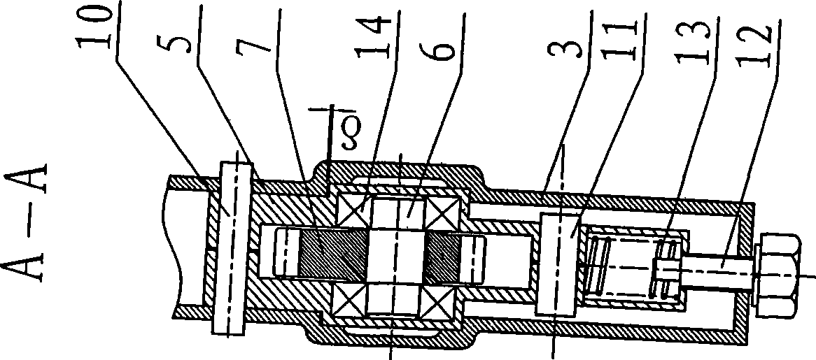
[0020] like figure 1 , 2 As shown, the present invention comprises the same left and right transmission boxes of the structure respectively installed at the two ends of the central axis 1, and the planting arms installed on the left and right transmission boxes. The structure in the right transmission box body 3 is as follows: the right center non-circular gear 4 which is vacantly sleeved on the right end of the central shaft 1 is fixedly connected with the frame through the tooth-embedded right flange 2, on both sides of the right center non-circular gear 4, The upper and lower right intermediate non-circular gears 7 fixed on the upper and lower right intermediate shafts 6 and the upper and lower right planetary non-circular gears 9 fixed on the upper and lower right planetary shafts 8 are installed symmetrically in sequence, and the upper and lower right planetary ge...


PUM


Abstract

The present invention discloses a non- cylindrical gear transmission system separating insertion mechanism which can eliminate the tooth space. Two ends of central shaft are respectively installed with a left transmission box body and a right transmission box body which have same structure. A central non- cylindrical gear which is freely sleeved on two ends of central shaft is fixedly connected with a frame through a jaw flange. The two sides, the upper part and lower part of the central non- cylindrical gear are equally symmetrically installed with an intermediate non- cylindrical gear and a planet non- cylindrical gear sequentially. One end of planet shaft is fixed with a planting arm. The shaft center of five shafts are arranged with two congruence triangles which are opposite through the intermediate shaft when seen from the side surface. Two ends of intermediate shaft are movably supported in the base hole of transmission box body through the shaft hub of adjusting sleeve. A clearance delta is provided between the shaft hub and the base hole of adjusting sleeve, or a spring piece is installed in the shaft hole of intermediate shaft of transmission box body for eliminating the tooth side clearance among the central gear, the intermediate gear and the planet gear. The non- cylindrical gear transmission system separating insertion mechanism of the invention structurally has the advantages of large gear module and small box body, etc. The non- cylindrical gear transmission system separating insertion mechanism also has the advantages of adjustable tooth space, smooth transmission, small seedling insertion cavity and good erection property of seedling. The non- cylindrical gear transmission system separating insertion mechanism is especially suitable for the operation requirement of high-speed seedling transplanter.

Description

technical field [0001] The invention relates to agricultural machinery, in particular to a non-circular gear drive train splitting mechanism capable of eliminating backlash. Background technique [0002] In the existing published literature on the transplanting mechanism of the rice transplanter, there are two arrangements of the central gear, the intermediate gear and the planetary gear in the non-circular gear transmission mechanism: linear and triangular. The advantage of linear arrangement is that the initial installation angle is easy to determine, and the design and calculation are more convenient. However, its volume and shape are relatively large, and it is only suitable for high-speed rice transplanters. Compared with the linear arrangement, the triangular shape can be designed to be smaller, and the gear modulus can be selected to be larger, which is conducive to improving the strength of the gear teeth. By optimizing the relevant parameters, it can be used for bo...

Claims


Application Information

Patent Timeline
Patent Type & Authority Applications(China)
IPC IPC(8): A01C11/02
Inventor 张国凤赵匀赵雄
Owner ZHEJIANG SCI-TECH UNIV
Why Eureka
Try Eureka