
Double-main shaft double-speed compound numerical control milling machine

A CNC milling machine and double-spindle technology, applied in the field of mechanical processing, can solve the problems of dependence on imports, large output torque, and high price, and achieve the effects of improving processing efficiency, reducing costs, and compact and reasonable structure

Inactive Publication Date: 2009-08-12
周勇
View PDF0 Cites 27 Cited by
  • Summary
  • Abstract
  • Description
  • Claims
  • Application Information

AI Technical Summary

Problems solved by technology

It has large output torque, high processing efficiency, and multiple functions such as milling, drilling, boring, reaming, and tapping. It has strong rigidity and stability, strong heavy cutting ability, and the spindle speed of ordinary machining centers Usually lower than 8000rpm, due to the low spindle speed, high-speed precision machining cannot be performed, and the surface finish of the processed workpiece is poor
High-speed machining centers, because of the built-in high-speed spindle, the spindle speed can reach more than 20,000rpm, which can be used for fast machining, high-precision and ultra-fine surface machining of parts, but due to the limitation of the characteristics of the motor, it is generally not suitable for low-speed powerful machining
This kind of high-speed machining center basically relies on imports at present, and the price is expensive

Method used


Image

  • Double-main shaft double-speed compound numerical control milling machine
  • Double-main shaft double-speed compound numerical control milling machine
  • Double-main shaft double-speed compound numerical control milling machine

Examples


Embodiment Construction

[0016] Attached below figure 1 , figure 2 , image 3 , Figure 4 , Figure 5 , the present invention is further described:

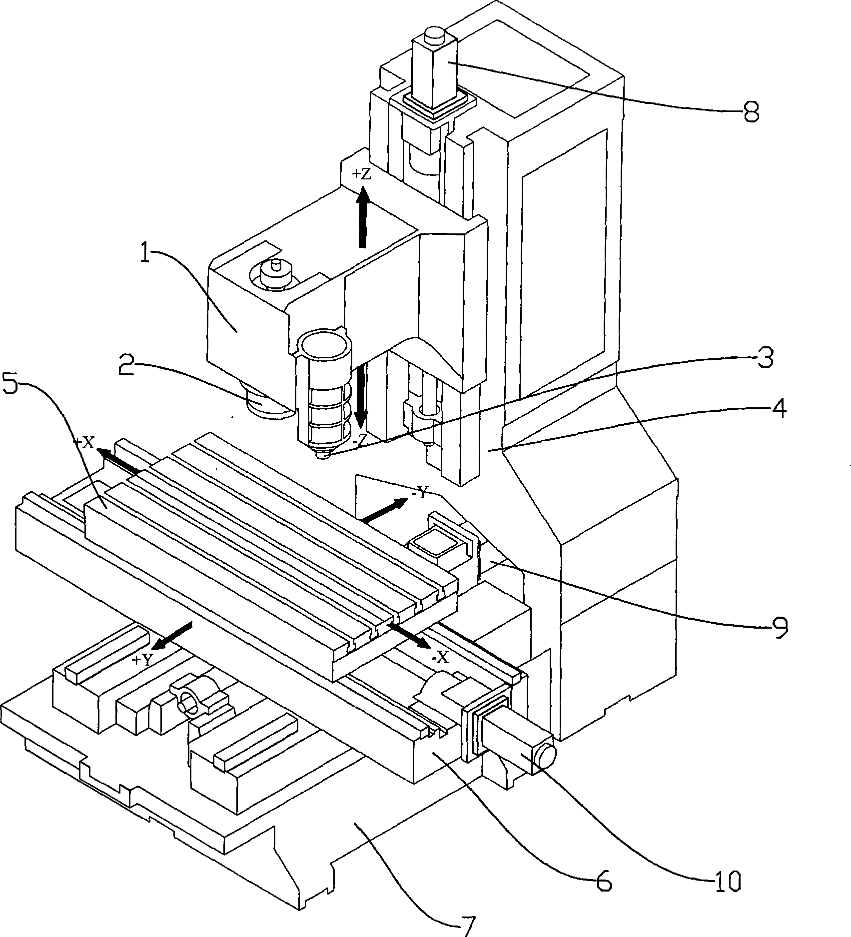
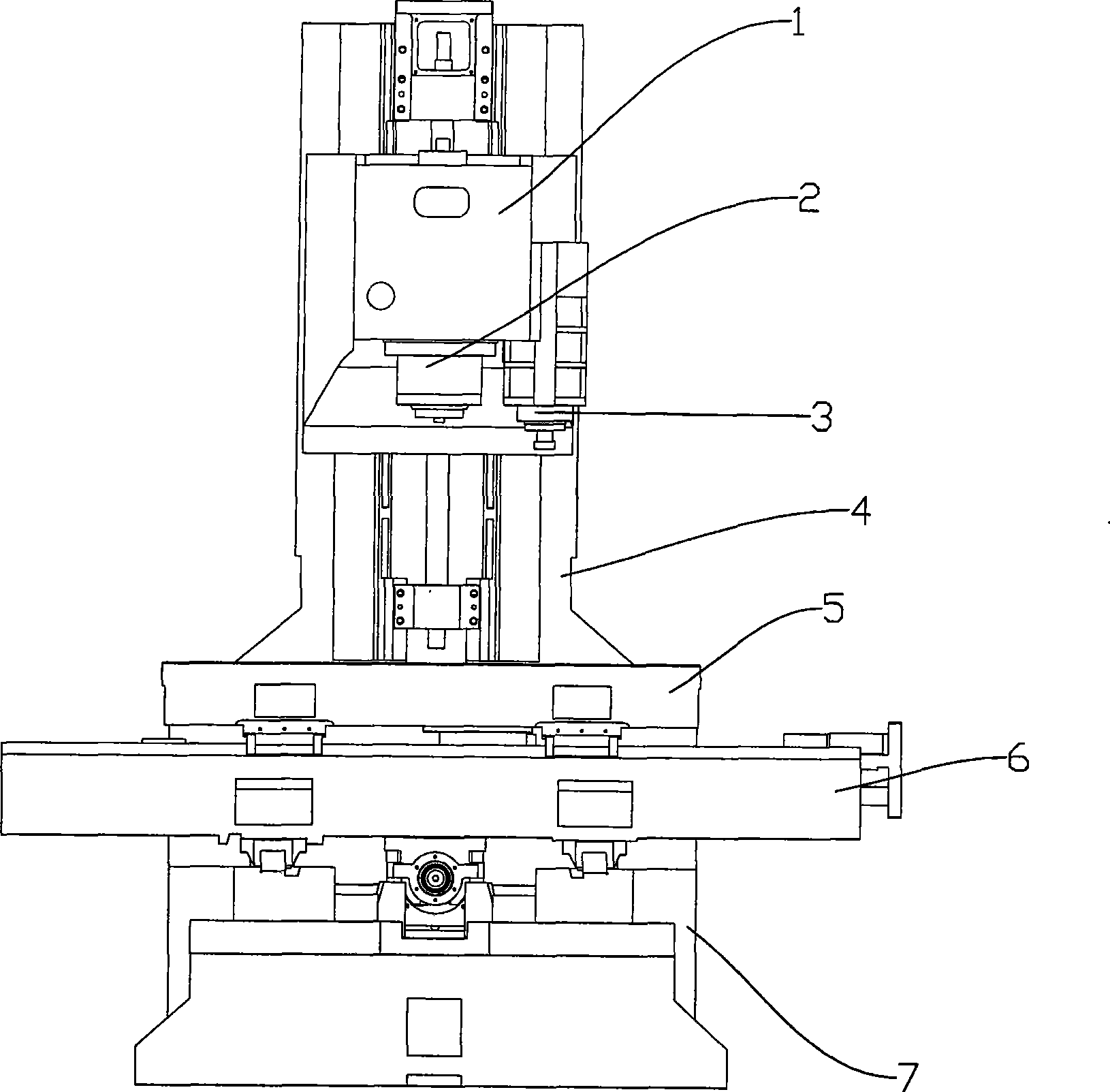
[0017] as attached figure 1 , figure 2 As shown in the figure, the present invention includes a headstock 1 that can install two main shafts, the main power main shaft 2 and a high-speed electric main shaft 3 are installed on the headstock 1, and are used for supporting and making the column 4 that the side of the headstock can slide, Workbench 5, machine tool saddle 6 and machine body 7, and realize the motor of machine tool transmission, screw pair and numerical control system. The main power spindle 2 is a machining center spindle capable of powerful milling, drilling, boring, reaming, tapping, etc.; such a main power spindle can be a machining center spindle in the prior art. In order to realize the overall movement of the main power spindle 2 and the high-speed electric spindle 3 in the vertical direction, the main power spindle 2 and the h...


PUM


Abstract

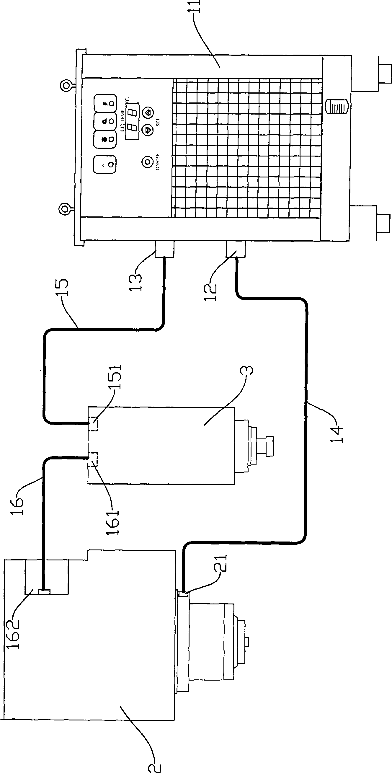
The invention provides a double-spindle and double-speed composite NC milling machine and pertains to the field of mechanical processing technology. The invention consists of a main power spindle, a high-speed motorized spindle, a spindle box for arranging the main power spindle and the high-speed motorized spindle, an upright column, a workbench, a bed saddle, a bed body, a servo motor, a servo drive and a NC system. The invention is characterized in that the main power spindle and the high-speed motorized spindle are arranged in the spindle box; the spindle box is supported on the guide rail of the column and can slide along a guide rail; an X-shaft motor is arranged on the bed saddle so that the workbench can move horizontally and a Y-shaft motor is arranged on the bed body so that the bed saddle can move back and forth; a Z-shaft motor is arranged on the column to drive the spindle box to move in a straight-line way; the NC system consists of a controller, a system input I / O unit, a system output I / O unit, a servo amplifying unit and a system bus for connecting these parts; a cooling system is a series-wound oil cooling circuit. The invention increases the processing efficiency and also reduces the cost.

Description

Technical field: [0001] The invention relates to a double-spindle double-speed composite numerical control milling machine, which belongs to the technical field of mechanical processing. Background technique: [0002] In the field of metal cutting, ordinary vertical milling centers are widely used. It has large output torque, high processing efficiency, and multiple functions such as milling, drilling, boring, reaming, and tapping. It has strong rigidity and stability, strong heavy cutting ability, and the spindle speed of ordinary machining centers Usually lower than 8000rpm, due to the low spindle speed, high-speed precision machining cannot be performed, and the surface finish of the processed workpiece is poor. High-speed machining centers, because of the built-in high-speed spindle, the spindle speed can reach more than 20,000rpm, which can be used for fast machining, high-precision and ultra-fine surface machining of parts, but due to the characteristics of the motor,...

Claims


Application Information

Patent Timeline
IPC IPC(8): B23C1/08
Inventor 周勇罗勇刚
Owner 周勇
Learn More