Solar battery welding device and welding process

A technology for welding equipment and solar cells, applied in welding equipment, metal processing equipment, circuits, etc., can solve problems such as thermal deformation of silicon wafers, hidden cracks and fragments of silicon wafers, so as to avoid high temperature thermal shock, improve welding efficiency, and reduce The effect of production costs

Active Publication Date: 2009-08-12
WUXI SUNTECH POWER CO LTD
View PDF0 Cites 15 Cited by
  • Summary
  • Abstract
  • Description
  • Claims
  • Application Information

AI Technical Summary

Problems solved by technology

Under the trend of thinning, the thickness of silicon wafers used in solar cells is getting thinner and thinner. The thickness of monocrystalline silicon wafers is generally reduced to 160 microns, while the thickness of polycrystalline silicon wafers has reached 180 microns. Therefore, traditional manual welding is used in production. There will be some unstable factors in the process, such as causing the silicon wafer to be deformed by local high temperature heating, resulting in cracks or even fragments of the silicon wafer; in addition, since the silicon wafer will inevitably bend during the solar cell production process, and automatic welding is generally It also adopts the method of local heating and welding, so the scrap rate of machine automatic welding is relatively high

Method used


Image

  • Solar battery welding device and welding process
  • Solar battery welding device and welding process
  • Solar battery welding device and welding process

Examples


Embodiment Construction

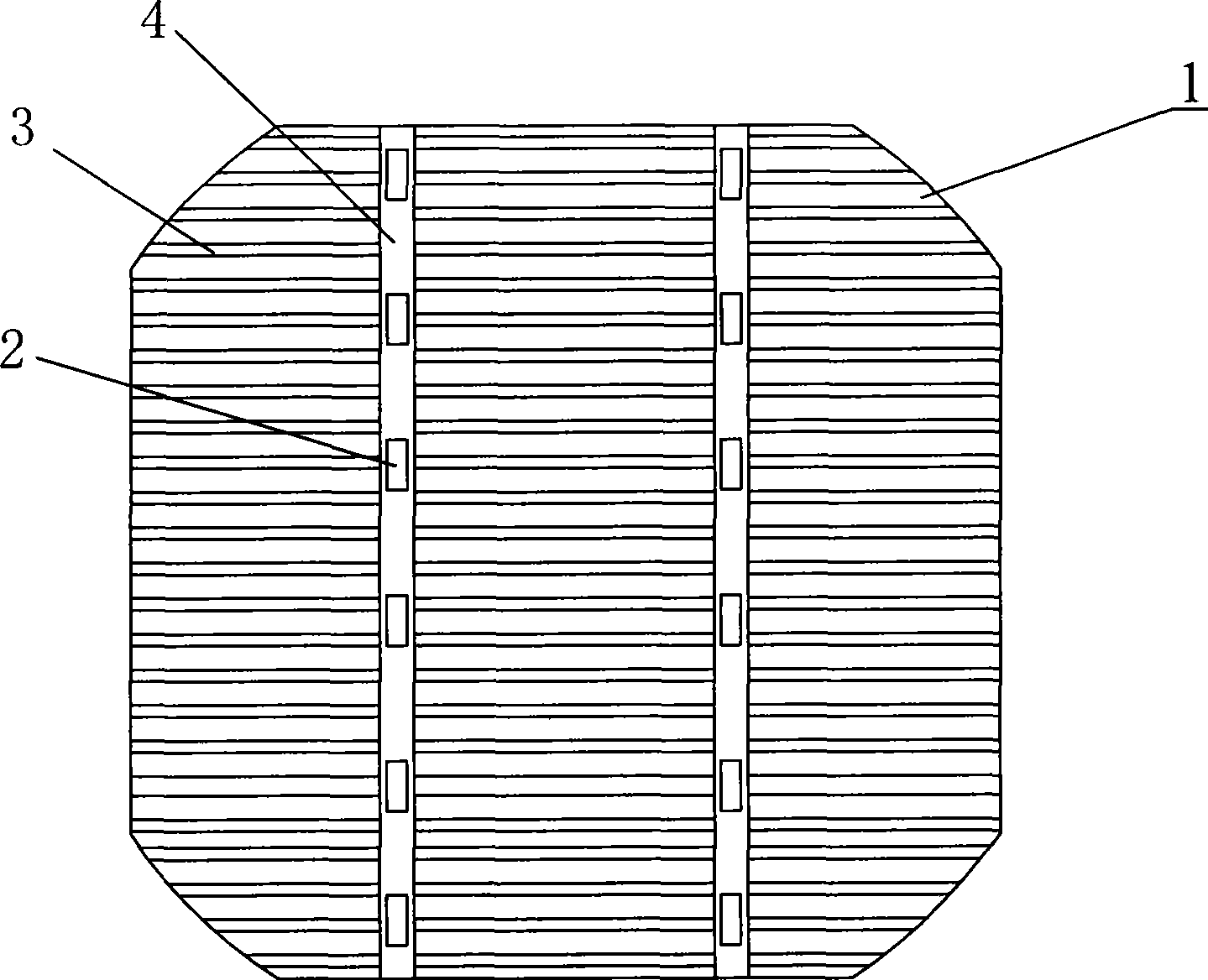
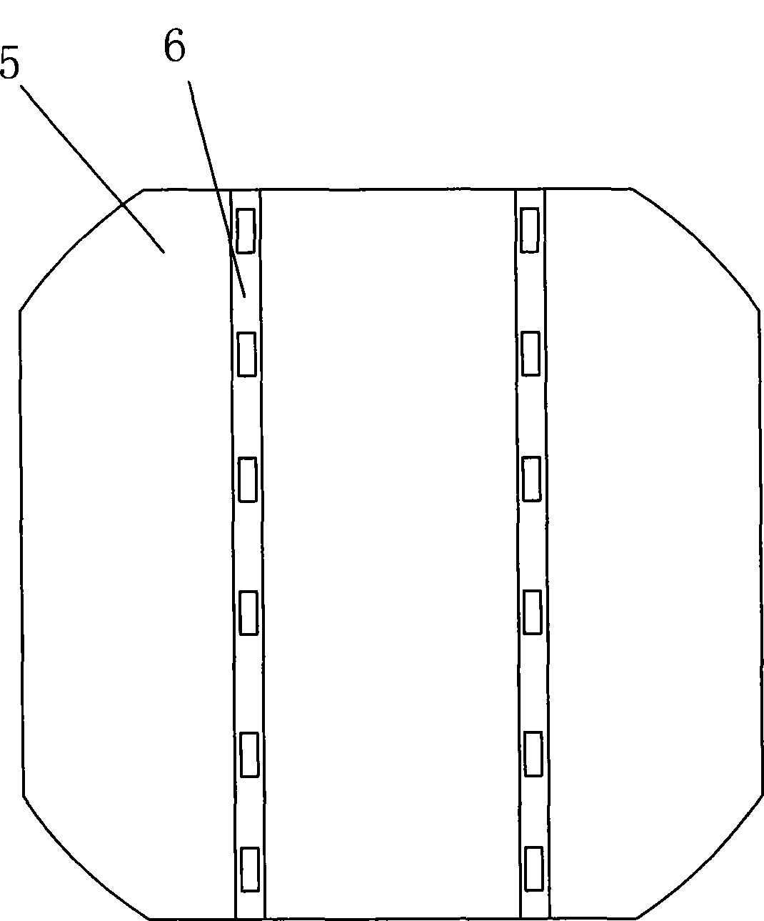
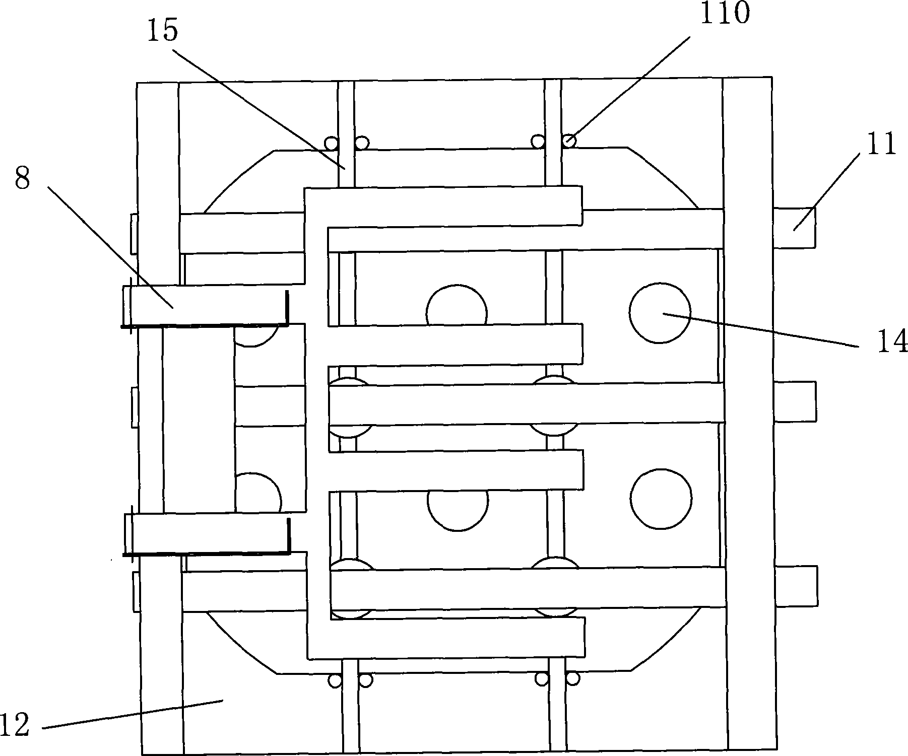
[0026] figure 1 Shown is a schematic diagram of the front side 1 of the solar battery sheet 9, including the main grid??? line 4, the auxiliary grid line 3 and the solder paste 2, wherein the main grid??? line 4 is orthogonal to the auxiliary grid??? line 3, The solder paste 2 is printed on the sub-grid??? line 3 at intervals; figure 2 Shown is a schematic view of the back of the solar cell 9 , including a back electric field 5 , a back electrode 6 and solder paste 2 printed on the back electrode 6 at intervals. The welding equipment of the present invention includes the fixing fixture of the cell sheet 9 and the heating and welding furnace, please refer to image 3 , Figure 4 , Figure 5 and Image 6 , image 3 Shown is a schematic diagram of the fixing fixture of the first embodiment of the present invention, Figure 4 for image 3 right view of the Figure 5 shown as image 3 The schematic diagram of the fixture and the fixing of the battery sheet, Image 6 for ...


PUM

PropertyMeasurementUnit
thicknessaaaaaaaaaa

Abstract

The invention relates to the field of solar battery production, in particular to a solar battery welding device and a welding technology. The welding device consists of a battery patch stationary fixture and a heating welding furnace. At least two positioning grooves in parallel for positioning interconnected strips are arranged on a pedestal of the stationary fixture; a lower press strip is arranged above the positioning grooves of the interconnected strips for positioning a lower interconnected strip; an upper press strip is arranged above the lower press strip for positioning an upper interconnected strip. The invention can increase the welding efficiency of the battery patch, decrease the damage to silicon slices and reduce the waste, which is applicable to batch production of solar battery modules.

Description

technical field [0001] The invention relates to the field of solar cell manufacturing, in particular to a solar cell welding device and a welding process. Background technique [0002] As an emerging green energy, solar photovoltaic power generation has been widely used. Since the output power of a single solar cell is relatively small, generally the individual solar cells are welded one by one using interconnection bars to form a solar cell module with a relatively large output power. The welding method currently used is manual welding. Under the trend of thinning, the thickness of silicon wafers used in solar cells is getting thinner and thinner. The thickness of monocrystalline silicon wafers is generally reduced to 160 microns, while the thickness of polycrystalline silicon wafers has reached 180 microns. Therefore, traditional manual welding is used in production. There will be some unstable factors in the process, such as causing the silicon wafer to be deformed by lo...

Claims


Application Information

Patent Timeline
Patent Type & Authority Applications(China)
IPC IPC(8): B23K1/008B23K3/00H01L31/18
CPCY02P70/50
Inventor 王赟汪义川
Owner WUXI SUNTECH POWER CO LTD
Why Eureka
Try Eureka