Acoustic emission sensor

An acoustic emission sensor and preamplifier technology, which is applied in the parts of grinding machine tools, metal processing equipment, grinding/polishing equipment, etc. The effect of improving sensitivity, eliminating interference, and improving response sensitivity

Active Publication Date: 2011-02-09
NANJING UNIV +1
View PDF0 Cites 0 Cited by
  • Summary
  • Abstract
  • Description
  • Claims
  • Application Information

AI Technical Summary

Problems solved by technology

This kind of sensor does not need to use couplant, but its structural complexity is greatly increased, and it inherits the shortcomings of contact sensors that are susceptible to noise interference from the grinding machine itself. Moreover, once the cooling water is interrupted or contains air bubbles, the reliability of the collected signals cannot be guaranteed.
[0006] The non-contact AE sensor has capacitive type and optical fiber type, which respectively measure the capacitance change or optical path interference effect caused by the vibration of a certain plane on the grinding machine due to the acoustic emission phenomenon. Since the measurement is still the vibration on the grinding machine, it will inevitably be affected. The noise interference of the grinding machine itself
Moreover, the capacitive sensor measures capacitance and is susceptible to environmental interference; while the fiber optic sensor system is huge, requires a laser as a light source, and the signal processing is slow, so the application limitations are very large
[0007] To sum up, the existing AE sensors, either directly or indirectly, measure the acoustic signal transmitted through the grinding machine itself when the grinding machine is grinding, and the grinding machine or cooling water is required as the sound transmission medium, so the vibration noise of the grinding machine itself cannot be avoided Or the noise interference of the cooling water, so that accurate measurement cannot be obtained; and the acoustic emission sensor of the prior art has a complex structure and is inconvenient to install and use

Method used


Image

  • Acoustic emission sensor
  • Acoustic emission sensor

Examples


Embodiment Construction

[0019] The present invention will be further described below in conjunction with the accompanying drawings.

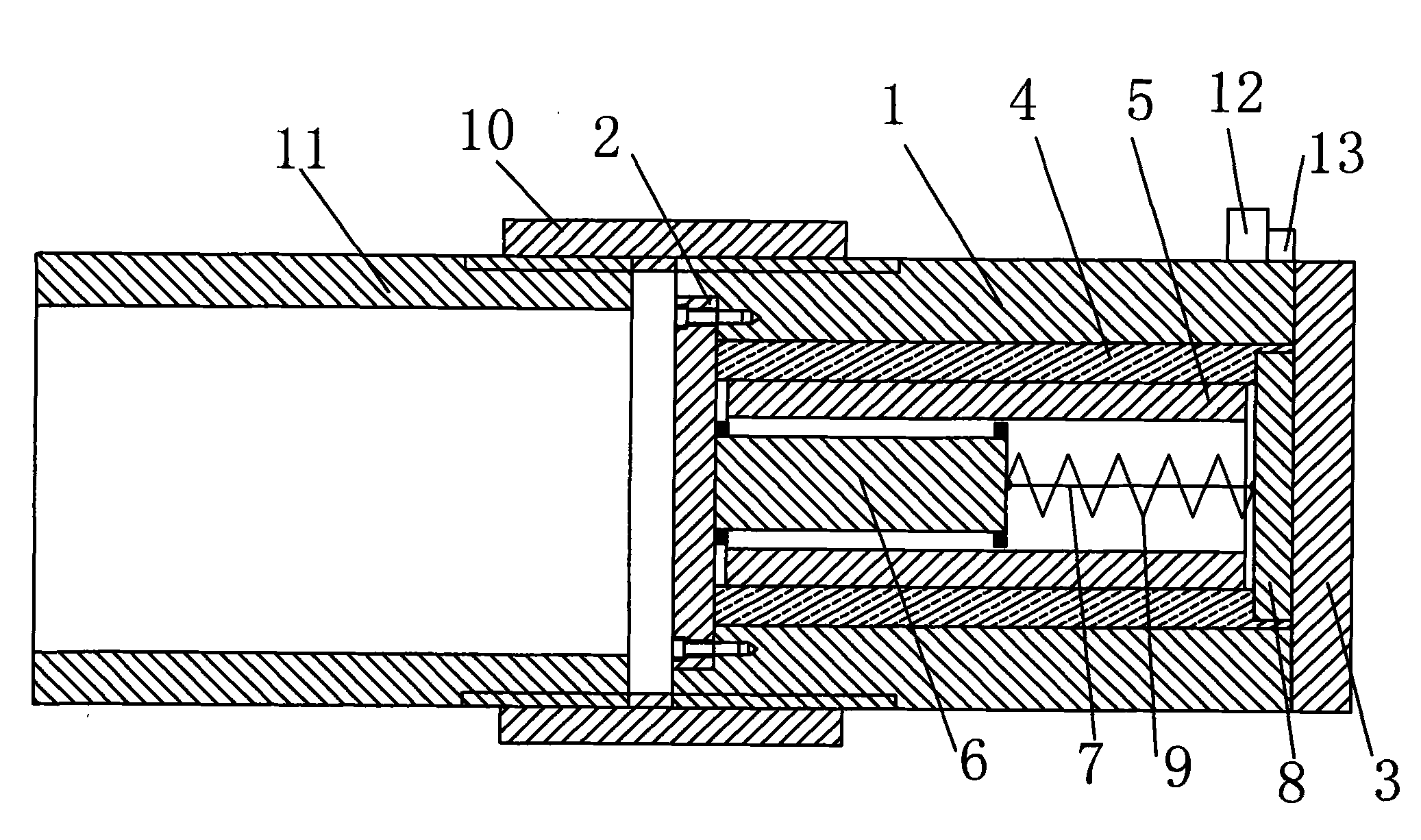
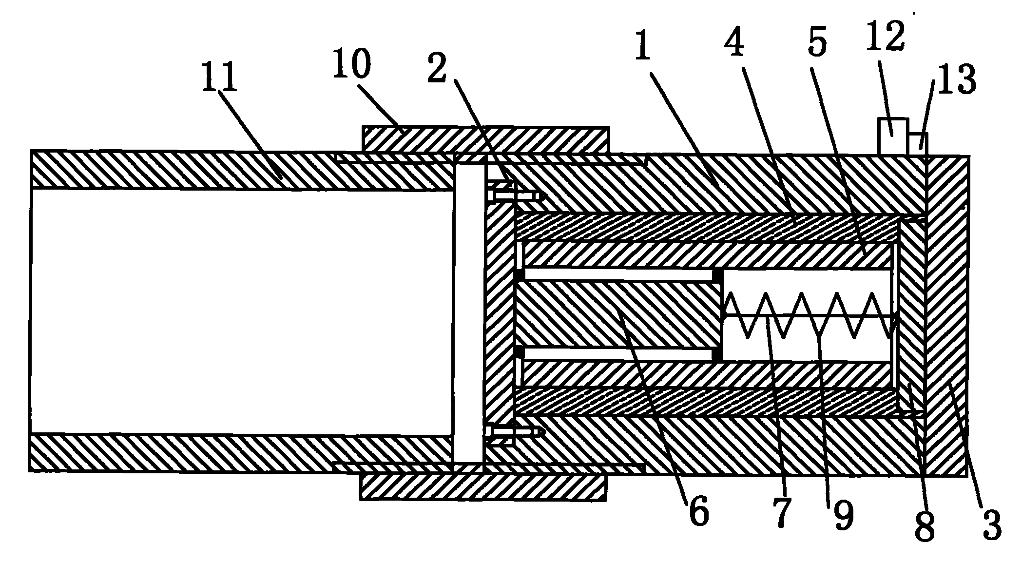
[0020] As shown in the figure, the acoustic emission sensor of the present invention includes a housing 1, a front cover 2, a rear cover 3, a filling sleeve 4, a piezoelectric element sleeve 5, a piezoelectric element 6, a wire 7, and a preamplifier 8 , Spring 9, connecting sleeve 10, fixing sleeve 11, power connector 12 and signal output terminal 13.

[0021] One end of the housing 1 is fixed with a front cover 2, and the housing 1 is a cylinder made of hard aluminum alloy. One end surface of the housing 1 has an annular groove along the center, and the front cover 2 is a circular thin plate whose diameter and thickness match the diameter and thickness of the groove on the end surface of the housing 1, that is, the front cover 2 Pressed in the groove, the plane of the front cover 2 and the end surface of the housing 1 are in the same horizontal plane. The front cove...


PUM


Abstract

The invention discloses an acoustic emission sensor. One end of a casing is provided with a front cover, and the other end of the casing is provided with a back cover plate; the inner wall of the cavity of the casing is provided with a filling sleeve, and the inner wall of the filling sleeve is provided with a piezoelectric element sleeve; the front end of the piezoelectric element is arranged onthe front cover plate by a conductive adhesive tape which is covered on the piezoelectric element, the back end of the piezoelectric element is arranged on a circuit board of a preamplifier by a spring, a conductive adhesive tape is covered between the back end of the piezoelectric element and the spring, one end of a conductor is welded on the conductive adhesive tape on the back end of the piezoelectric element, and the other end of the conductor is welded on an input end of the preamplifier; the circuit board of the preamplifier is fixed on the back cover plate. The acoustic emission sensor is used for receiving grinding sound signals transmitted by air, directly eliminates interferences of machine noises on effective signals and has the advantages of reasonable structure, convenient usage, high sensitivity, wide response frequency band and low price.

Description

technical field [0001] The invention relates to an acoustic emission broadband air sensor used in a numerical control grinder grinding acoustic emission monitoring system. Background technique [0002] Acoustic emission sensor, also known as AE sensor, is a sensor for acoustic emission detection of structural damage. It can be used in the grinding acoustic emission monitoring system of CNC grinding machines. The acoustic emission sensor is used to receive the AE (Acoustic Emission) signal, distinguish the quality of the grinding state, quantify the grinding state, give a decision on how to modify the grinding parameters in order to optimize the grinding state, and provide a basis for the control system. [0003] Traditional AE sensors include three types: contact, semi-contact and non-contact. [0004] The contact AE sensor uses a piezoelectric element to convert the acoustic signal into an electrical signal. It is fixed on the workbench or cooling water nozzle with a fixtu...

Claims


Application Information

Patent Timeline
Patent Type & Authority Patents(China)
IPC IPC(8): B24B49/10
Inventor 贲宇张仲宁刘翔雄
Owner NANJING UNIV
Why Eureka
Try Eureka