Fluorescent molecular tomography method suitable for small animals

A technology of fluorescent molecular tomography and imaging methods, which is applied in the field of spectral technology applications, can solve the problems of no patents, etc., and achieve the effect of accurately positioning the position and intensity

Inactive Publication Date: 2009-08-19
HUAZHONG UNIV OF SCI & TECH
View PDF0 Cites 10 Cited by
  • Summary
  • Abstract
  • Description
  • Claims
  • Application Information

AI Technical Summary

Problems solved by technology

The finite element algorithm itself was developed in the analysis of structural mechanics. Later, with the deepening of theoretical research, people applied it to wider fields, such

Method used


Image

  • Fluorescent molecular tomography method suitable for small animals
  • Fluorescent molecular tomography method suitable for small animals
  • Fluorescent molecular tomography method suitable for small animals

Examples


example 1

[0064] This example is mainly to prove the accuracy of the finite element method mentioned in the patent of the present invention to calculate the propagation of fluorescence in the body. The specific steps are: put 10% intralipid (fat emulsion solution) into a glass container with a length of 46.3 mm, a width of 19.2 mm and a height of 60 mm. On one side of the glass container, a 632.8nm He-Ne laser is used to irradiate the glass container vertically. On the other side of the glass container, a high-performance cooling CCD is used to record the light intensity. The optical parameters of the 10% fat emulsion solution mentioned in the literature are

[0065] 532NM 650NM 632.8NM

[0066] Absorption coefficient (1 / cm) 0.02 0.0023 0.0029

[0067] Scattering coefficient (1 / cm) 640 320 350

[0068] reduced scattering coefficient

[0069] (1 / cm) 109 59.9 61.1

[0070] Anisotropy factor 0.825 0.823 0.829

[0071] Table 1 Optical parameters of 10%...

example 2

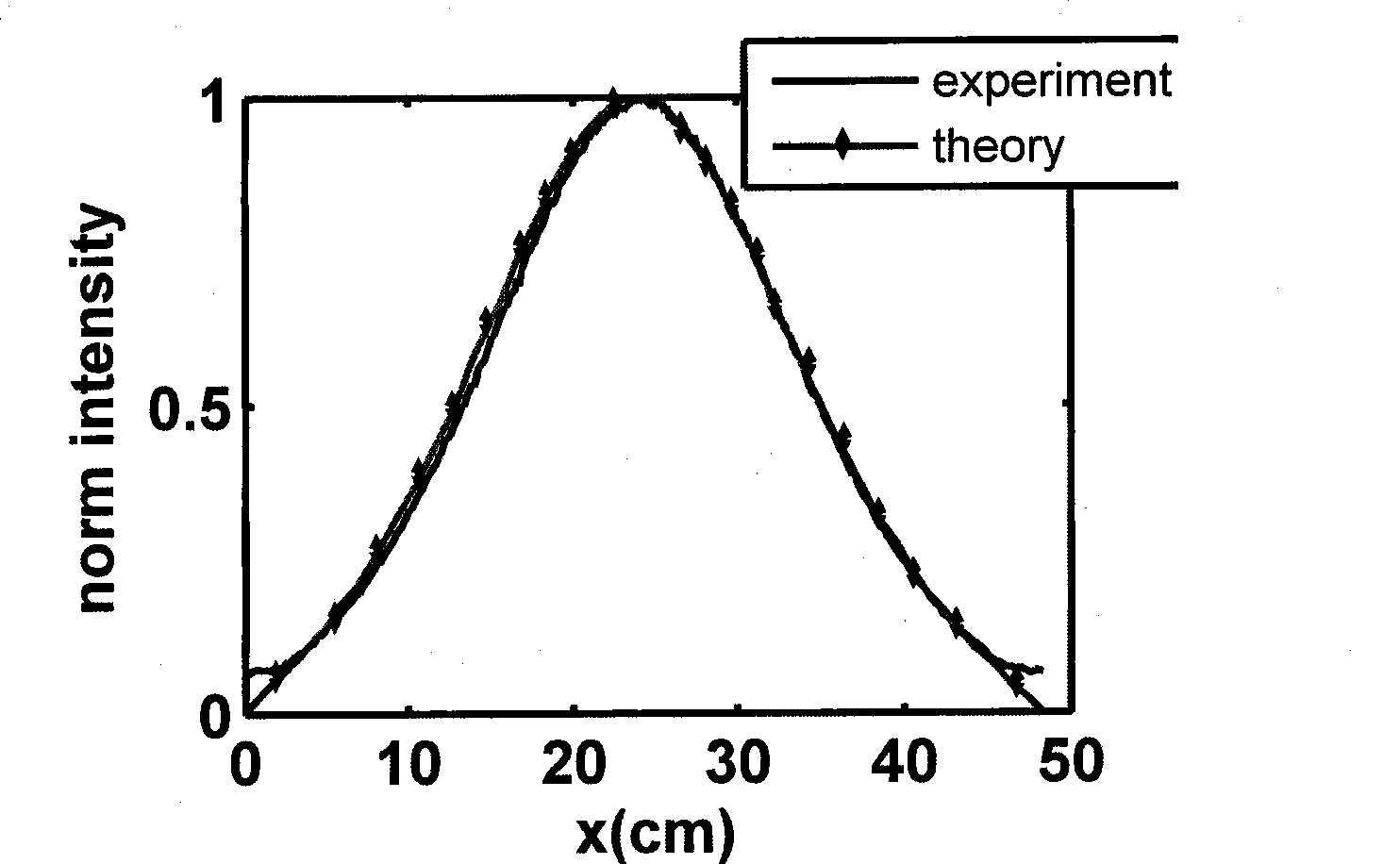
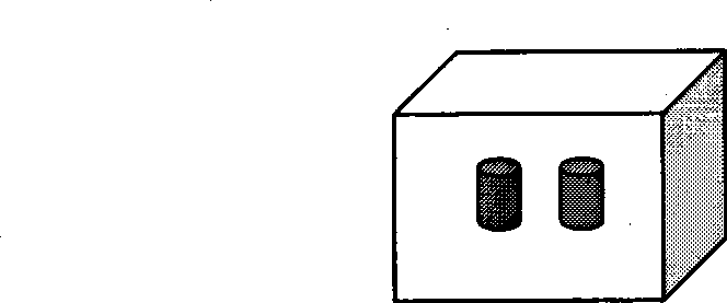
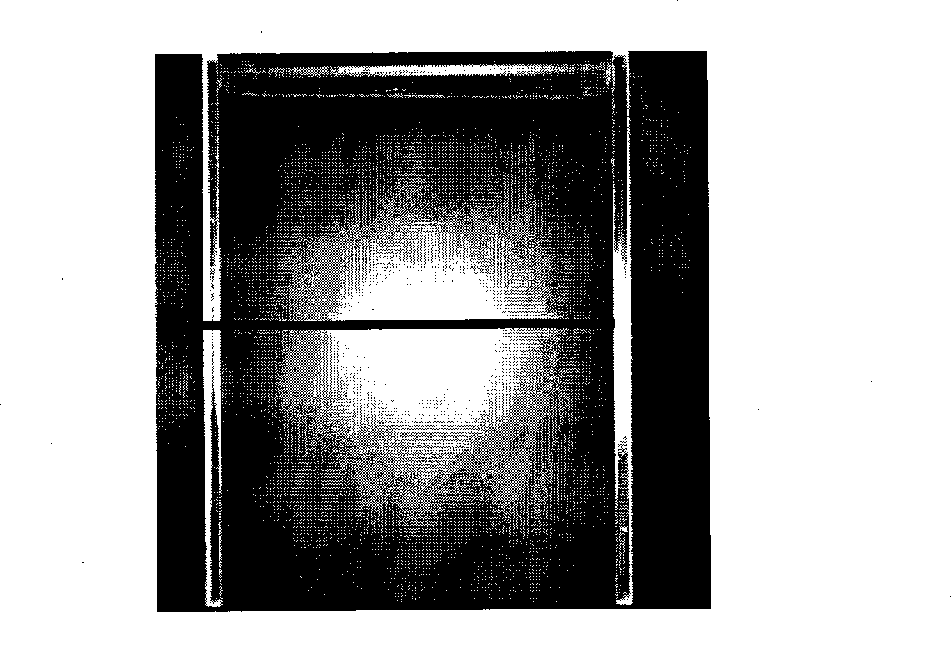
[0074] This example mainly demonstrates that the method of this patent can be used to localize fluorescent markers in vivo. The specific steps are: put a pair of glass tubes (distance between 4.1mm and 2mm inner diameter of the glass tubes) equipped with quantum dot fluorescent markers into a glass container filled with 10% intralipid solution, the container is 46.3mm long and 19.2mm high 60mm, as attached figure 2 shown. Irradiate the glass container vertically with a 632.8 nm He-Ne laser. Then record the fluorescent light intensity on the other side of the glass container with a high-performance cooling CCD. Move the position of the laser 6 times, 2mm to the left each time. At the same time, a high-performance cooling CCD is used to record the fluorescence light intensity on the other side of the glass container. Then change the spacing of the glass tubes to 3.2mm, 2.1mm, 0.9mm, and repeat the above experiment process. Finally, the experimental data as D e , μ αe ,D ...

example 3

[0076] This example mainly proves that the method mentioned in this patent can be used to quantitatively detect the concentration of fluorescent markers. The specific steps are: a glass tube (with a distance of 4.1 mm and an inner diameter of 2 mm) equipped with a 100% concentration quantum dot fluorescent marker ) into a glass container containing 10% intralipid solution (7mm from the glass surface). The container is 46.3mm long, 19.2mm wide and 60mm high, as attached figure 2 shown. Irradiate the glass container vertically with a 632.8 nm He-Ne laser. Then record the fluorescent light intensity on the other side of the glass container with a high-performance cooling CCD. Move the position of the laser 6 times. Move 2mm to the left each time. At the same time, a high-performance cooling CCD is used to record the fluorescence light intensity on the other side of the glass container. Then change the concentration of quantum dot markers in the glass tube to 80%, 70%, 50%, ...


PUM


Abstract

The invention relates to the application of spectroscopic techniques in the field of biomedical engineering, in particular to a fluorescence molecule tomographic imaging method which is applicable to small animals, which describes a fluorescence propagation process in tissues in a approximately precise degree by utilizing the diffusion of a radioactive transfer equation, computes fluorescence distribution in the tissues by adopting a finite element method, back-deduces the concentration and position of a fluorescent marker by combining a nonlinear optimizing algorithm, and finally implements the display of fluorescence molecule tomographic imaging through computer graphic processing. The fluorescence molecule tomographic imaging method can locate the position and concentration of the fluorescent marker deep inside the tissues of small animals based on corresponding instrument measured data, and realize tomographic imaging; and specially for deep fluorescent signals, the fluorescence molecule tomographic imaging method can accurately and quickly recover the depth and intensity information that is carried by the deep fluorescent signals, thus achieving the accurate locating effect of the fluorescent marker position and intensity and providing reference means to medicine development and tumor treatment.

Description

technical field [0001] The invention belongs to the application of spectrum technology and the field of biomedical engineering, and relates to a fluorescent molecular tomographic imaging method for detecting the position of a fluorescent marker molecule in a small animal body and quantitatively detecting the concentration of a fluorescent marker molecule in a small animal body. Background technique [0002] With the development of bioluminescent protein and bioluminescent labeling technology, targeted fluorescent markers are increasingly used in tumor detection and drug development. This improves the drug development cycle and the accuracy of tumor detection to a certain extent. However, due to the complexity of the propagation process of fluorescence in biological tissue, it does not propagate in a straight line in tissue like X-rays. Due to the strong scattering properties of tissue to visible light, the light entering the tissue and the light excited from the tissue Fluo...

Claims


Application Information

Patent Timeline
IPC IPC(8): G01N21/64
Inventor 骆清铭龚辉全国涛邓勇
Owner HUAZHONG UNIV OF SCI & TECH
Why Eureka
Try Eureka