Polarization dual wavelength fiber-optical ultrashort pulse laser

An ultrashort pulse and fiber laser technology, applied in the field of optical information, can solve the problems of difficult to achieve passive mode-locked ultrashort laser pulse, small adjustment range, small spectral interval, etc.

Inactive Publication Date: 2011-07-20
JIANGSU SKYERALASER TECH
View PDF4 Cites 0 Cited by
  • Summary
  • Abstract
  • Description
  • Claims
  • Application Information

AI Technical Summary

Problems solved by technology

The disadvantages are: 1. The spectral interval of the two different reflection peaks (with different polarization states) caused by the inherent large birefringence of the polarization maintaining fiber is relatively small and the adjustment range is small; 2. Due to the narrow bandwidth Polarization-maintaining fiber grating is used as the reflective surface of the laser cavity, so it is difficult to realize passive mode-locking to generate ultra-short laser pulses; 3. This cavity structure is suitable for narrow-linewidth tunable dual-wavelength fiber lasers
Jian Liu, Ultrshort StableMode-locked Fiber Laser At One Micron By Using PolarizationMaintaining(PM)Fiber and Photonic Bandgap Fiber(PBF), US Patent, US2008 / 0151945A1, Hong Lin, Wavelength Tunable, Polarization StableMode-locked Fiber Laser, World International Property Organization, PCT / US00 / 19170, 2001 and O.Okhotnikov et al, A Mode-Locked Fiber Laser, World International Property Organization, PCT / FI2006 / 050184, 2006, etc. about passive mode-locked fiber laser ultrashort optical pulse generation Although international patents also use polarization-maintaining rare-earth-doped fibers as gain media, they are only aimed at single-wavelength ultrashort pulse laser output and do not involve dual-wavelength mode-locked fiber lasers.

Method used


Image

  • Polarization dual wavelength fiber-optical ultrashort pulse laser
  • Polarization dual wavelength fiber-optical ultrashort pulse laser
  • Polarization dual wavelength fiber-optical ultrashort pulse laser

Examples


Embodiment 1

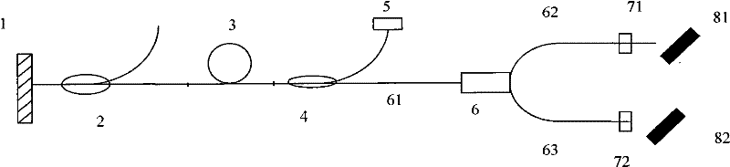
[0076] The cavity structure of a polarized dual-wavelength fiber ultrashort pulse laser provided in this embodiment adopts a section of polarization-maintaining rare-earth-doped gain fiber as the gain medium, and uses a polarization beam splitter (PBS) to separate laser beams with two different polarization directions As a long wave (λ 1 ) and shortwave (λ 2 ) laser oscillation tuning arm, the rare earth-doped fiber is doped with rare earth element Nd 3+ 、Pr 3+ , Yb 3+ 、Er 3+ and Tm 3+ Optical fiber; the optical fiber is one of ordinary single-mode polarization-maintaining rare-earth-doped optical fiber, multi-layer pumped rare-earth-doped large-core single-mode polarization-maintaining optical fiber or rare-earth-doped polarization-maintaining large-core single-mode photonic crystal optical fiber. Please refer to the attached Figure 1 to Figure 5 .

[0077] See attached figure 1 , the first cavity shape is to directly use a grating as a dual-wavelength laser cavity t...

Embodiment 2

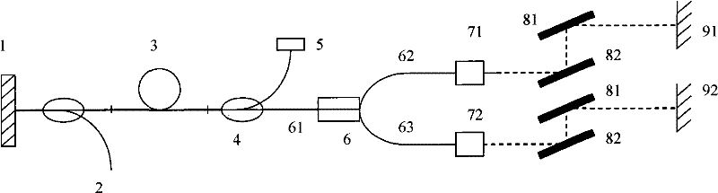
[0083] The cavity structure of a polarization dual-wavelength fiber ultrashort pulse laser provided in this embodiment is to use a polarization beam splitter (PBS) to separate the light of two different polarization directions into long-wave (λ 1 ) and shortwave (λ 2 ) of the laser oscillation tuning arm, using two polarization-maintaining doped rare-earth fibers with different lengths, and the two dual-wavelength laser tuning arms as gain media. Rare earth doped fiber is doped with rare earth element Nd 3+ 、Pr 3+ , Yb 3+ 、Er 3+ and Tm 3+ Optical fiber; the optical fiber is one of ordinary single-mode polarization-maintaining rare-earth-doped optical fiber, multi-layer pumped rare-earth-doped large-core single-mode polarization-maintaining optical fiber or rare-earth-doped polarization-maintaining large-core single-mode photonic crystal optical fiber. Please refer to the attached Figure 6 ~ Figure 10 .

[0084] See attached Image 6 , the first cavity structure is: th...

Embodiment 3

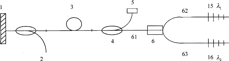
[0090] The cavity structure of a polarized dual-wavelength fiber ultrashort pulse laser provided in this embodiment is characterized in that a section of rare earth-doped non-polarization-maintaining gain fiber is used as the gain medium, and a polarization beam splitter (PBS) divides two different The laser light in the polarization direction is regarded as the long wave (λ 1 ) and shortwave (λ 2 ) laser oscillation tuning arm. Rare earth doped fiber is doped with rare earth element Nd 3+ 、Pr 3+ , Yb 3+ 、Er 3+ and Tm 3+ Optical fiber; the optical fiber is an ordinary single-mode non-polarization-maintaining rare-earth-doped optical fiber, a multi-layer pumped rare-earth-doped large-core single-mode non-polarization-maintaining optical fiber or a rare-earth-doped non-polarization-maintaining large-core single-mode photonic crystal fiber A sort of. Please refer to the attached Figure 11 ~ Figure 12 .

[0091] See attached Figure 11 , the cavity of the first structur...


PUM


Abstract

The invention discloses a polarized dual-wavelength fiber ultrashort pulse laser. The structure of the ultrashort pulse laser adopts polarization-preserving or common rare earth doped fiber as a laser gain dielectric, and utilizes a polarized beam splitter to split light, a broadband chirped fiber grating as a cavity surface reflecting element and a dispersive compensation element and a semi-conductor saturable absorption body as a mode locking element, to generate a fiber laser with high repetition frequency, high power, simple structure and high efficiency, which is a laser realizing the full fiber dual-wavelength mode locking fiber ultrashort laser pulse output. The ultrashort pulse laser has output of picosecond and femtosecond light impulse length polarized laser, with the wavelengthof more than 1 micrometer; the laser, after being amplified by a high-power dual-wavelength fiber amplifier, can be used for substituting a two-color wavelength mode locking titanium sapphire laser and a two-color wavelength mode locking titanium sapphire amplifier with large volume, complex operation and low efficiency, for utilizing beat frequency to generate a mid-infrared ultrashort pulse laser with the wavelength of about 15 micrometers and for pump-detection ultrafast optical physics experiments of a molecular system or environmental monitoring and detection of microwave photonics and biophysics and the like.

Description

technical field [0001] The invention relates to a fiber laser, in particular to a passive mode-locked fiber laser with high pulse repetition rate dual-wavelength ultrashort optical pulse output, which is suitable for generating ultrashort pulse mid-infrared laser radiation by direct difference frequency method for molecular systems Scientific experiments such as pumping and detection, environmental monitoring, microwave photonics and biophysical detection, etc., belong to the field of optical information technology. Background technique [0002] Today's scientific experiments such as pumping and detection of molecular systems, environmental monitoring, microwave photonics and biophysical detection require mid-infrared light sources with high average power ultrashort pulses. In recent years, with the development of solid-state laser media such as tunable Ti:sapphire laser technology, harmonic frequency conversion technology, and optical parametric oscillation and amplificatio...

Claims


Application Information

Patent Timeline
Patent Type & Authority Patents(China)
IPC IPC(8): H01S3/067H01S3/091H01S3/094H01S3/16H01S3/10H01S3/08H01S3/101G02B6/27G02B6/293
Inventor 刘东峰王钦华朱晓军余建军
Owner JIANGSU SKYERALASER TECH
Why Eureka
Try Eureka