PTC electric constant temperature container
A container and constant temperature technology, which is applied in the direction of instruments, heating devices, temperature control, etc., can solve the problems of inconvenient use of PTC constant temperature containers, and achieve the effects of reliable electrical connection, strong adaptability, and simple operation
- Summary
- Abstract
- Description
- Claims
- Application Information
AI Technical Summary
Problems solved by technology
Method used
Image

Examples
Embodiment 1
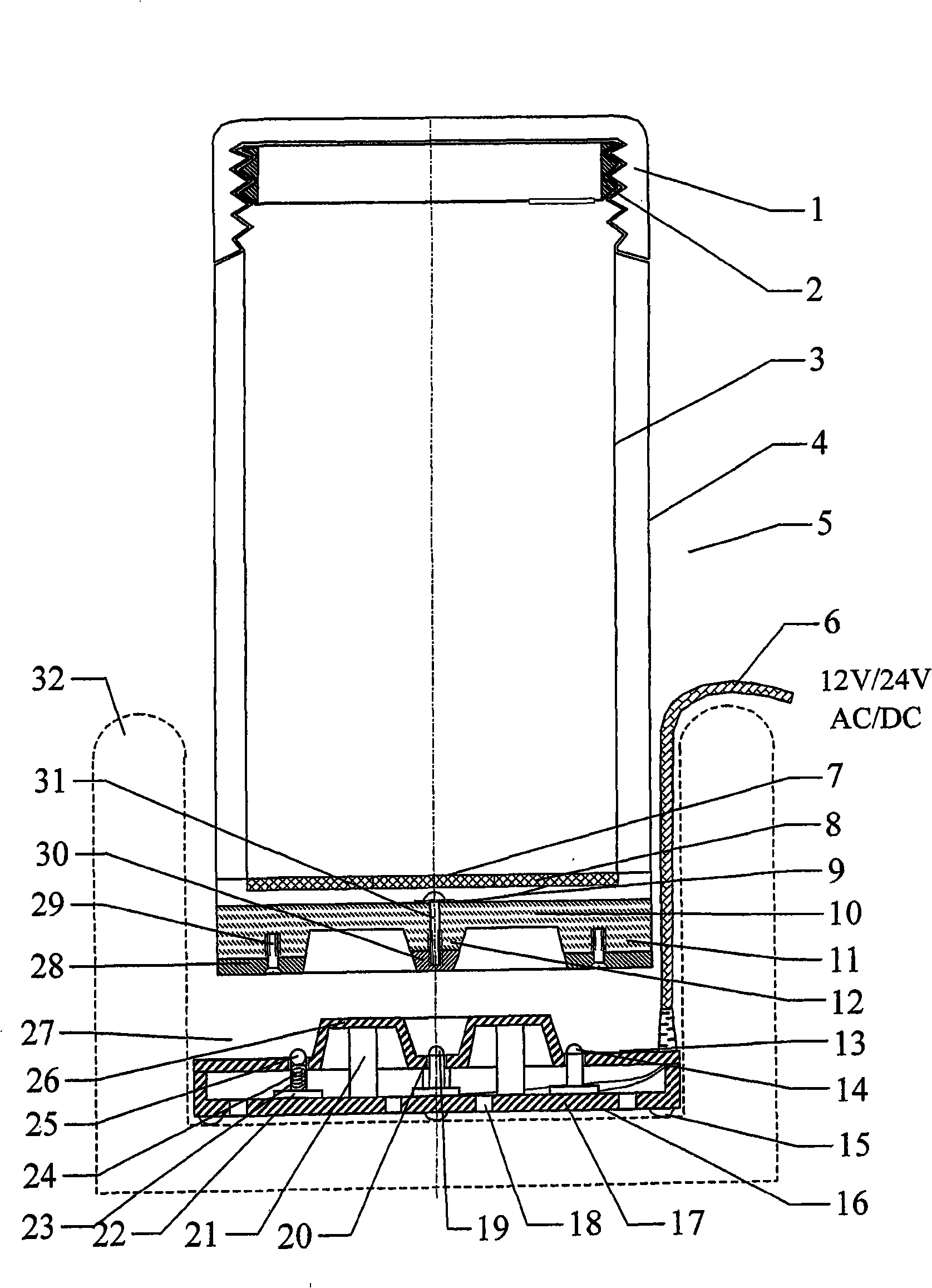
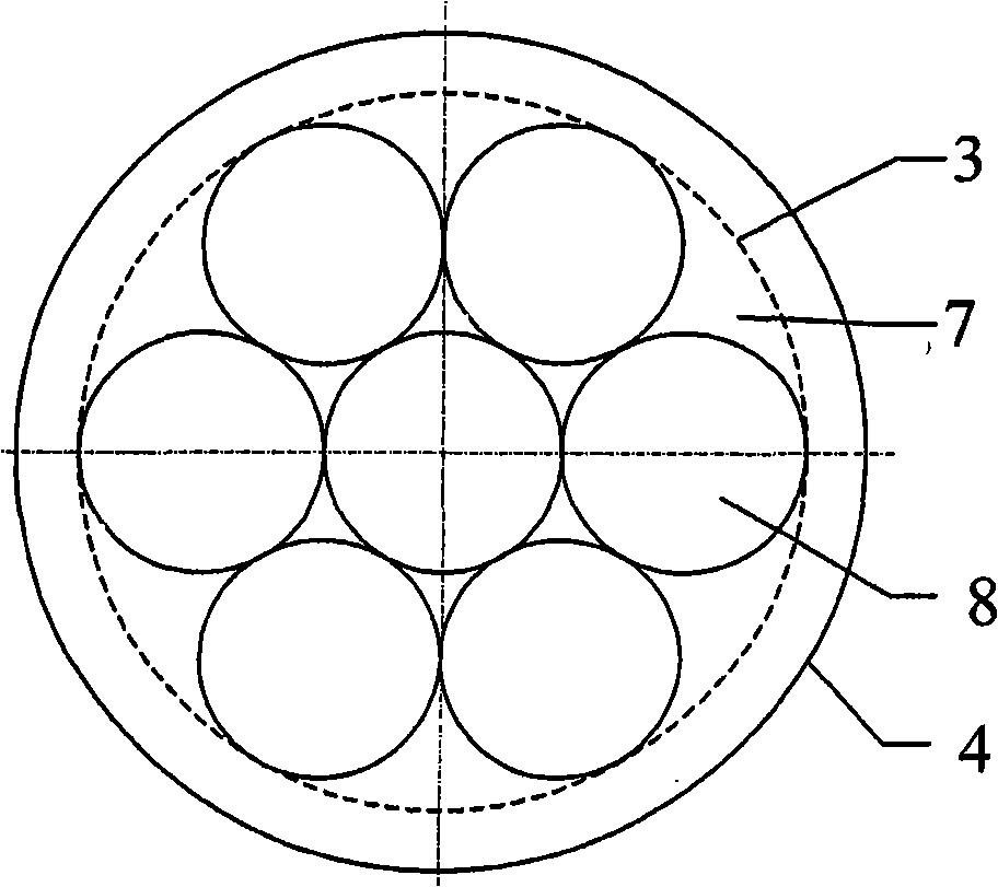
[0089] Such as figure 1 and 2 As shown, the PTC electric constant temperature cup 5 includes a cup inner bottom part 7, a cup outer bottom part 10, a cup inner wall 3, a cup outer wall 4 and a cup cover 1, etc. The cup inner bottom part 7 is made of stainless steel plate, seven of which are 20 mm in diameter and thick 1.5mm, the circular PTC heating element 8 is soldered or brazed on the underside of the cup insole 7, see figure 2 . The surface temperature of the PTC heating element 8 is 60±5°C, and the working voltage is 12V. The cup outer bottom part 10 is molded by plastic injection molding, and the center of its lower part is a frustum-shaped raised central electrode seat 12. The frustum-shaped central electrode pole shoe 30 at the lower end of the central electrode seat 12 is made of stainless steel, and the pole shoe passes through the center of the cup outer bottom part 10. One of the through holes is fixed with screw 31. The lower electrode layers of the seven PTC...
Embodiment 2
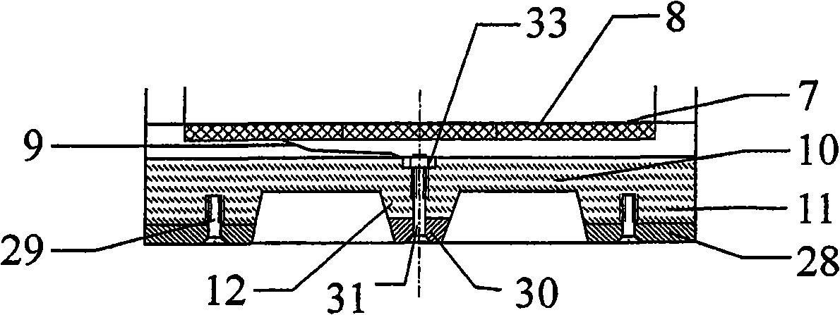
[0094] The difference between this embodiment and Embodiment 1 lies in the fixing method of the central electrode pole piece 30 of the cup outer bottom part, such as image 3 As shown, the screw 31 passes through the frustum-shaped central electrode pole shoe 30 with a through hole and the through hole of the cup outer bottom member 10 and the nut 33 on the upper part thereof is fixed, and is electrically connected with the electrode layer on the lower side of the PTC heating element 8 . The embodiment of the central electrode holder 12 and the central electrode pole piece 30 is defined as type B.
Embodiment 3
[0096] The difference between this embodiment and embodiment two is that the central electrode pole shoe 30 of the outer bottom of the cup, such as Figure 4 As shown, the shape of the frustum-shaped central electrode pole shoe 30 is changed from a conical shape to a conical shell shape, and the plastic circular frustum of the central electrode seat 12 matches it. The embodiment of the central electrode holder 12 and the central electrode pole piece 30 is defined as C-type.
PUM
 Abstract
Description
Claims
Application Information