Deformable aerofoil cover with changeable rigidity

A variable stiffness and skin technology, applied in the aerospace field, can solve the problems of poor skin's ability to receive aerodynamic loads, low overall wing carrying capacity, etc., to achieve high overall carrying capacity, improve various performance, and low requirements. Effect

Inactive Publication Date: 2009-08-26
HARBIN INST OF TECH
View PDF0 Cites 22 Cited by
  • Summary
  • Abstract
  • Description
  • Claims
  • Application Information

AI Technical Summary

Problems solved by technology

[0005] The purpose of the present invention is to solve the problem that the skin of the existing rubber-like material has poor aerodynam

Method used


Image

  • Deformable aerofoil cover with changeable rigidity
  • Deformable aerofoil cover with changeable rigidity
  • Deformable aerofoil cover with changeable rigidity

Examples


specific Embodiment approach 1

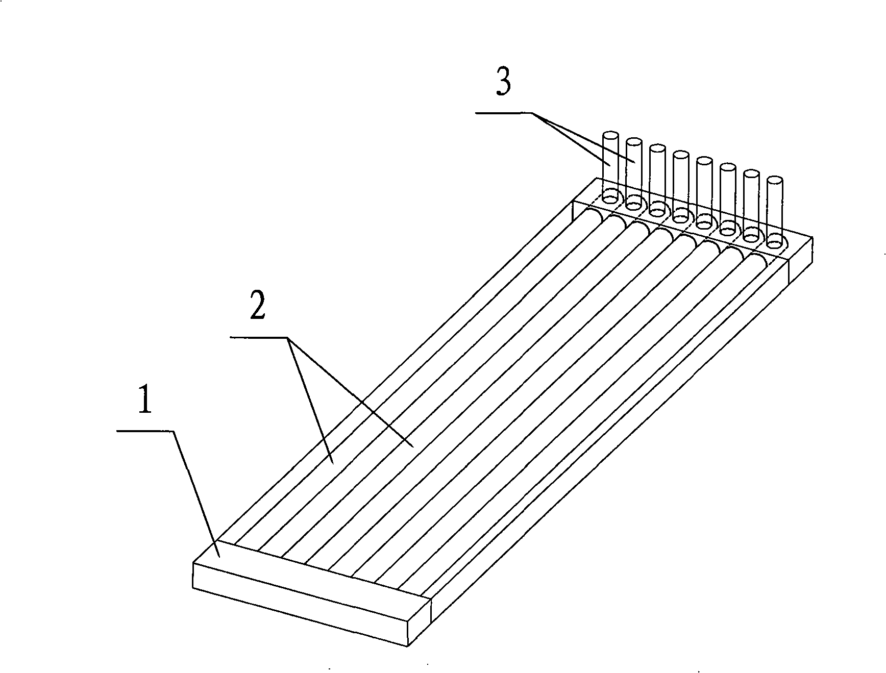
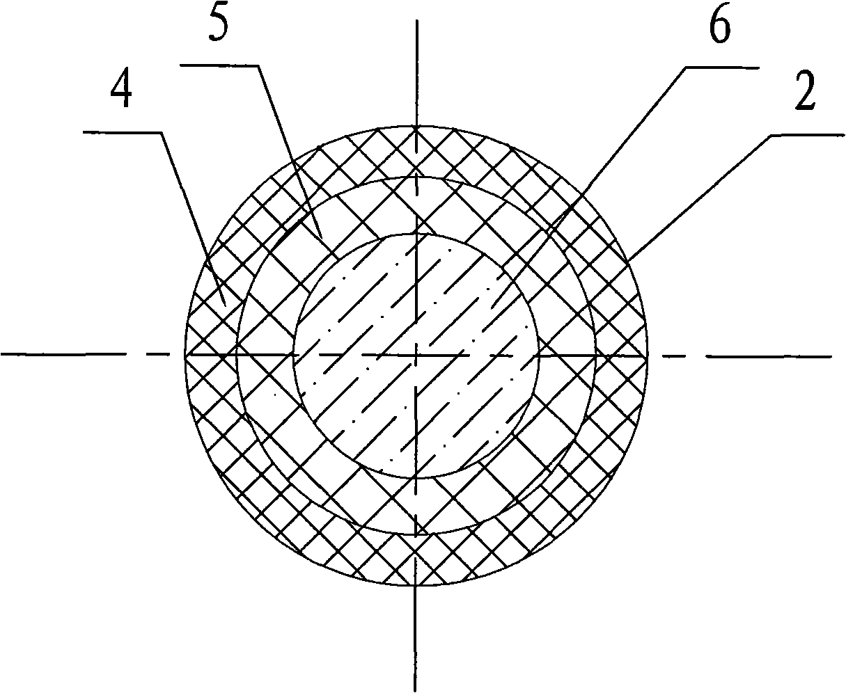
[0009] Specific implementation mode one: combine Figure 1 ~ Figure 2 Describe this embodiment, a deformed wing skin whose stiffness can be changed in this embodiment is composed of a silicon rubber skin base 1, a plurality of variable stiffness reinforcing tubes 2 and a plurality of control valves 3, and the plurality of variable stiffness reinforcing tubes The tubes 2 are embedded in the silicone rubber skin matrix 1 in parallel, and each control valve 3 is arranged on the outer surface of the silicone rubber skin matrix 1 and communicates with the corresponding variable stiffness reinforcing tube 2, and each variable stiffness reinforcing tube 2 has two The ends are all closed, and each of the variable stiffness reinforced pipes 2 is composed of a composite material outer layer 4, an inner liner pipe 5 and a working fluid 6, and the composite material outer layer 4 is wrapped on the outer surface of the inner liner pipe 5, The working fluid 6 is filled in the lining pipe 5 ...

specific Embodiment approach 2

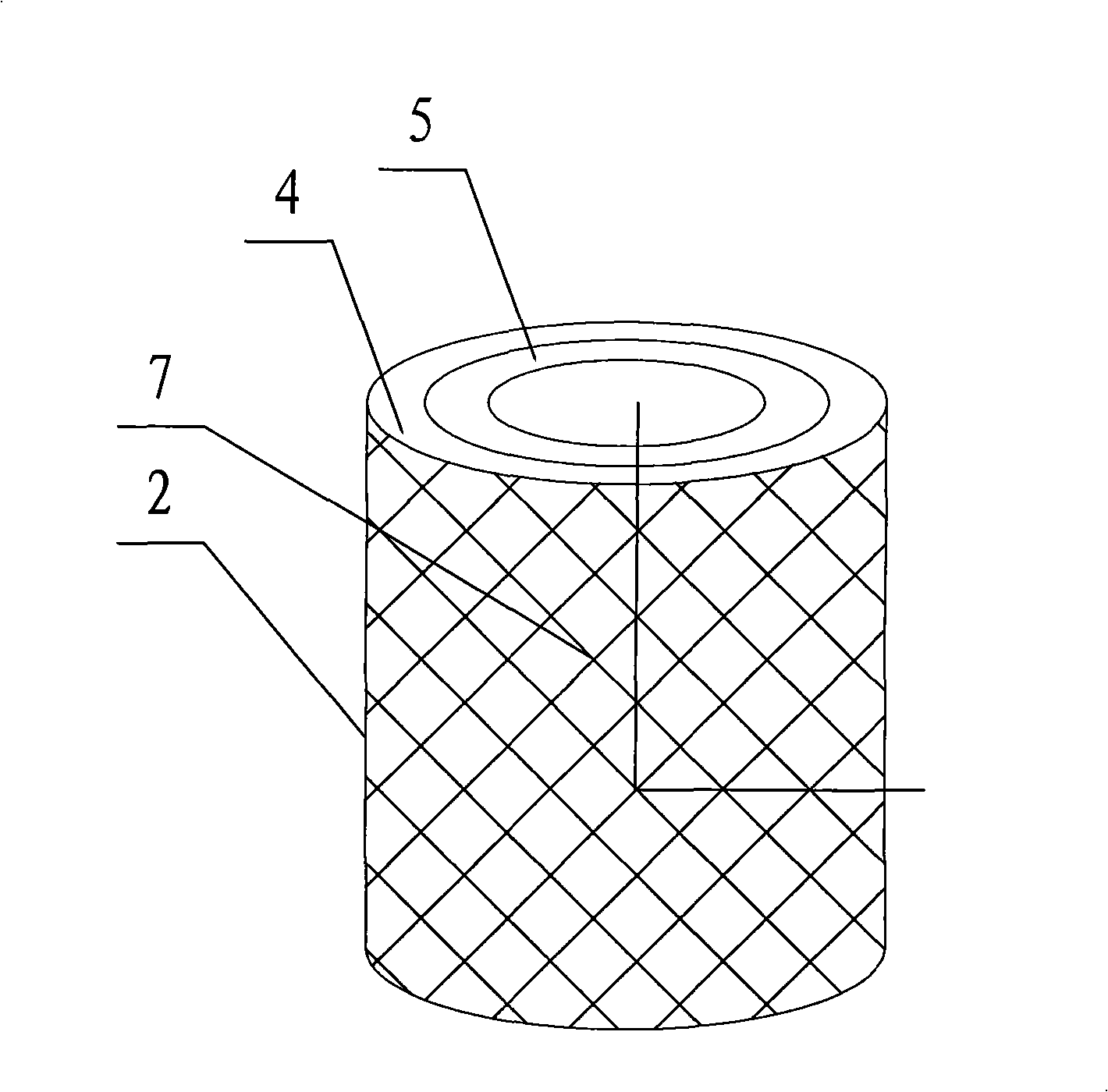
[0010] Specific implementation mode two: combination Figure 2 ~ Figure 3 To illustrate this embodiment, the outer layer 4 of the composite material in this embodiment is composed of a shape memory polymer matrix phase material and a reinforcement phase material; the reinforcement phase material accounts for 40% to 60% of the total volume of the outer layer 4 of the composite material; the reinforcement phase The fiber 7 of the material is compounded in the shape-memory polymer matrix phase material at an angle of 0°-90° to the radial direction of the variable-stiffness reinforced tube 2 . The shape memory polymer matrix material (SMP material) has a special memory function. When the SMP material is changed into a different shape layout, the SMP material molecules will reorganize to restore its original shape. The initial shape of the SMP material, That is to say that its "memory" shape is a rigid body, that is, a high modulus form. The SMP material used in the present inventi...

specific Embodiment approach 3

[0011] Specific implementation mode three: combination image 3 To describe this embodiment, the fiber 7 of the reinforcing phase material of this embodiment is compounded in the shape memory polymer matrix phase material at an angle of 20°-40° to the radial direction of the variable stiffness reinforcing tube 2 . With such arrangement, the rigidity of the variable-stiffness reinforcing tube 2 is better. Other components and connections are the same as those in the second embodiment.


PUM


Abstract

A deformable aerofoil cover with changeable rigidity relates to a deformable aerofoil cover. The invention solves the problem that the cover of the existing rubber material has poor capacity of bearing aerodynamic load and the problem of low entire bearing capacity of the aerofoil. In the invention, a plurality of reinforced pipes with changeable rigidity (2) are embedded into a silastic cover matrix (1) in parallel; each control valve (3) is arranged on the outer surface of the silastic cover matrix (1) and is communicated with the corresponding reinforced pipes with changeable rigidity (2); the two ends of each reinforced pipe with changeable rigidity (2) are all closed; each reinforced pipe with changeable rigidity (2) consists of a composite material outer layer (4), an inner liner pipe (5) and working liquid (6); the composite material outer layer (4) is coated on the outer surface of the inner liner pipe (5); and the working liquid (6) is filled in the inner liner pipe (5). The cover of the invention has strong capacity of bearing the aerodynamic load, and the entire loading capacity of the aerofoil is high, thus meeting the requirement of large-deformation of the deformable cover.

Description

technical field [0001] The invention relates to a deformed wing skin and belongs to the technical field of aerospace. Background technique [0002] Whether it is a flying animal or an artificial aircraft, in order to perform different tasks (such as cruise, hover, attack or escape, etc.), or to meet the different requirements of the flight environment (such as altitude, speed and climate, etc.), it often needs to be adjusted accordingly. To achieve high efficiency, safety and mission requirements. The traditional aircraft adopts the method of changing the shape of the wing through mechanical devices to adapt to different flight states such as take-off and landing, cruising and altitude flight, and strives to obtain more ideal performance. Flaps, variable sweep angle, variable airfoil camber or variable span length and other methods. However, the mechanical devices of traditional aircraft have complex mechanisms, limited functions, and low efficiency, making it difficult to...

Claims


Application Information

Patent Timeline
IPC IPC(8): B64C3/26B32B1/08B32B27/20C08L25/08C08L63/00C08L75/00C08L67/00C08L47/00C08L25/10C08L45/00C08K7/06C08K7/14C08K7/04
Inventor 冷劲松刘彦菊陈以金
Owner HARBIN INST OF TECH
Why Eureka
Try Eureka