Method and device for thermally processing sclerotized nonferrous metal wires

A technology for non-ferrous metals and wire rods, applied in heat treatment furnaces, heat treatment equipment, furnace types, etc., can solve problems such as hardening of non-ferrous metal wire rods, and achieve the effects of reducing annealing temperature, relieving pressure, and reducing use costs

Inactive Publication Date: 2009-09-02
韩富生
View PDF0 Cites 9 Cited by
  • Summary
  • Abstract
  • Description
  • Claims
  • Application Information

AI Technical Summary

Problems solved by technology

Provide a method that does not adopt heat treatment of finished products, but adopts online continuous intermediate heat treatment

Method used


Image

  • Method and device for thermally processing sclerotized nonferrous metal wires
  • Method and device for thermally processing sclerotized nonferrous metal wires
  • Method and device for thermally processing sclerotized nonferrous metal wires

Examples


Example Embodiment

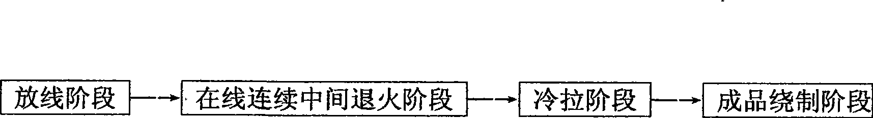
[0054] Example 1: Image 6 It is the process flow chart of the front-end online continuous intermediate annealing wire drawing machine; Figure 7 It is a schematic structural diagram of the front-line continuous intermediate annealing wire drawing machine according to the first embodiment of the present invention, Figure 8 It is a schematic diagram of the water sealing structure of the online continuous intermediate annealing wire drawing machine in the first embodiment of the present invention.

[0055] like Figure 7 and Figure 8 As shown, the front-end online continuous intermediate annealing wire drawing machine is composed of a wire-feeding device 22, an online continuous intermediate annealing device 21, a wire drawing host 20, a wire arrangement device 18, and a wire take-up device 19. The outlet end is placed on the top of the wire drawing host 20 and the rear transmission part of the wire arrangement 18 and the wire take-up device 19 with a low inclination.

[0...

Example Embodiment

[0059] Example 2: When the diameter of the non-ferrous metal wire hardened by cold work is thicker, the required annealing temperature is higher and the annealing time is longer, adding a preheating stage before the annealing stage is to achieve the same annealing effect under the same production speed condition Must have the best choice. Taking the wire drawing machine with preheating device as an example, the method of front online continuous intermediate preheating / annealing will be described in detail below.

[0060] Figure 9 It is a process flow diagram of the online continuous intermediate preheating / annealing method with a preheating stage applied to the cold drawing process of non-ferrous metal wires hardened by cold work, Figure 10 It is a schematic structural diagram of the online continuous intermediate preheating / annealing wire drawing machine according to the second embodiment of the present invention, Figure 11 It is a schematic diagram of the water sealing ...


PUM


Abstract

The invention discloses a method for first continuously annealing nonferrous metal wires in an on-line mode and then hard drawing the nonferrous metal wires. The method comprises the following steps of wire putting, on-line continuous middle annealing, drawing processing and wire arraying and collecting step. The invention has the advantages of putting forward a fire-new annealing process route and filling up the blank of the tinily drawing on-line continuous middle annealing process. Compared with the prior on-line continuous finished product heavy current annealing process used in the cable industry, the method can simplify the structure of equipment, reduce cooling water flow, install heat insulation facilities and leave out two process steps of external connection of protective gas and dryness of compressed air. Meanwhile, because non-contact annealing is adopted, the annealing quality is ensured. The device is easy to operate and maintain, has low manufacturing and use cost and can be applied to the whole cable industry, especially small and medium-sized enterprises. The on-line continuous middle annealing method is a novel basic processing technology capable of saving energy and water, improving quality and lowering cost in the cable industry.

Description

technical field [0001] The invention relates to a method for heat-treating non-ferrous metal wires hardened by cold work; in particular, after the non-ferrous metal wires are cold-drawn to produce hardening phenomenon, in the process of continuing cold-drawing process, online continuous heat treatment is carried out before continuous cold-drawing processing process methods and equipment. Background technique [0002] Non-ferrous metal wires are usually produced by cold drawing process. This process usually produces cold work hardening, which increases the difficulty of subsequent processing of finished products, or makes it difficult for non-ferrous metal wire and cable products to obtain excellent comprehensive mechanical properties, or makes non-ferrous metal wires and cables difficult to obtain. The metal wire loses its plasticity and cannot be further processed. In order to avoid this phenomenon, heat treatment is usually used to eliminate the cold work hardening phenome...

Claims


Application Information

Patent Timeline
IPC IPC(8): C21D9/52C21D1/26C22F1/00
Inventor 韩富生
Owner 韩富生
Why Eureka
Try Eureka