Isolation type power driving circuit

A power drive circuit, power drive technology, applied in electrical control, engine control, machine/engine, etc., can solve the problems of not using fault diagnosis measures, complex diagnosis circuit, etc., to solve electromagnetic compatibility and isolation of high-power drive problems , The structure is simple, the effect of the protection system

Inactive Publication Date: 2009-09-02
CHINA NORTH IND GRP NO 70 RES INST
View PDF0 Cites 14 Cited by
  • Summary
  • Abstract
  • Description
  • Claims
  • Application Information

AI Technical Summary

Problems solved by technology

For systems that require optoelectronic isolation drive, due to the complexity of the diagnostic circ

Method used


Image

  • Isolation type power driving circuit
  • Isolation type power driving circuit
  • Isolation type power driving circuit

Examples


Embodiment Construction

[0013] The preferred embodiments of the present invention will be further described below in conjunction with the accompanying drawings.

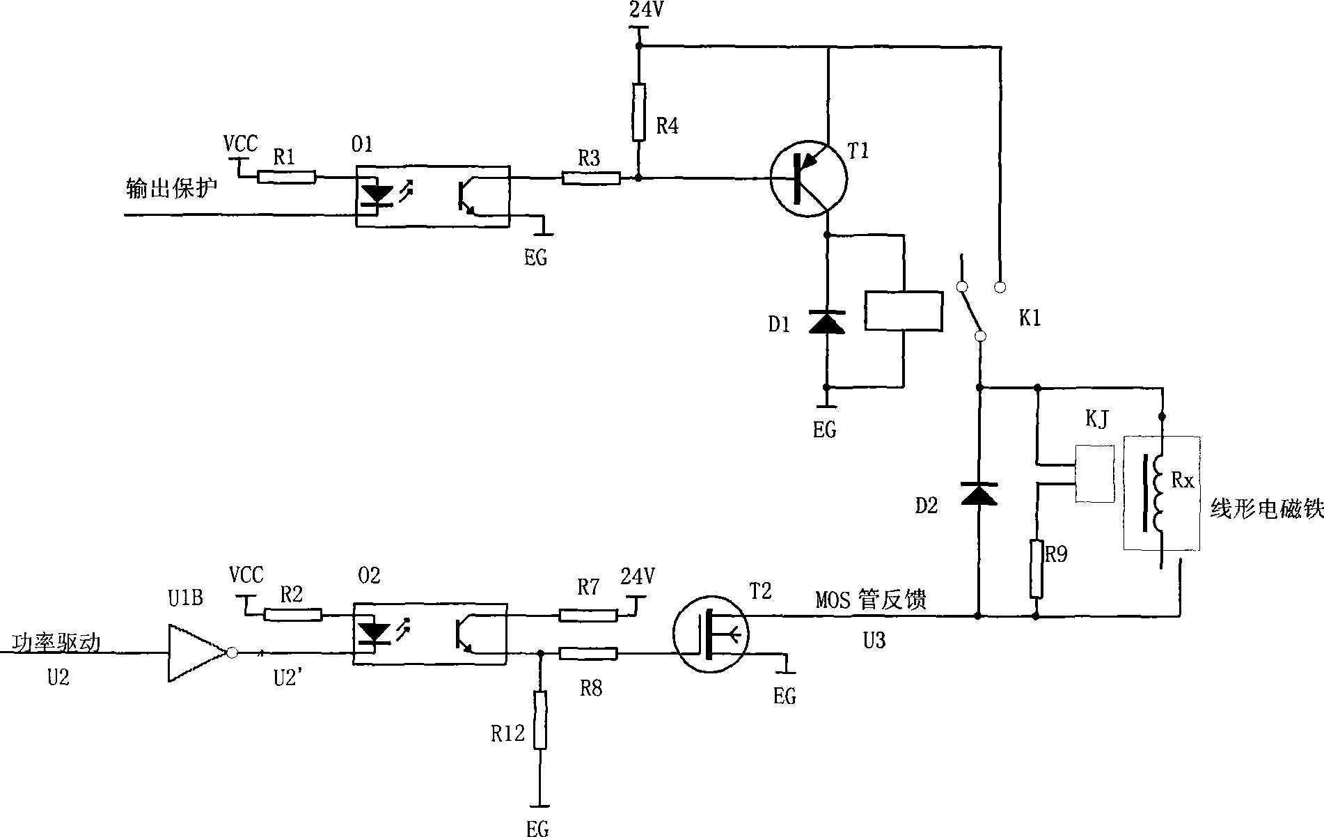
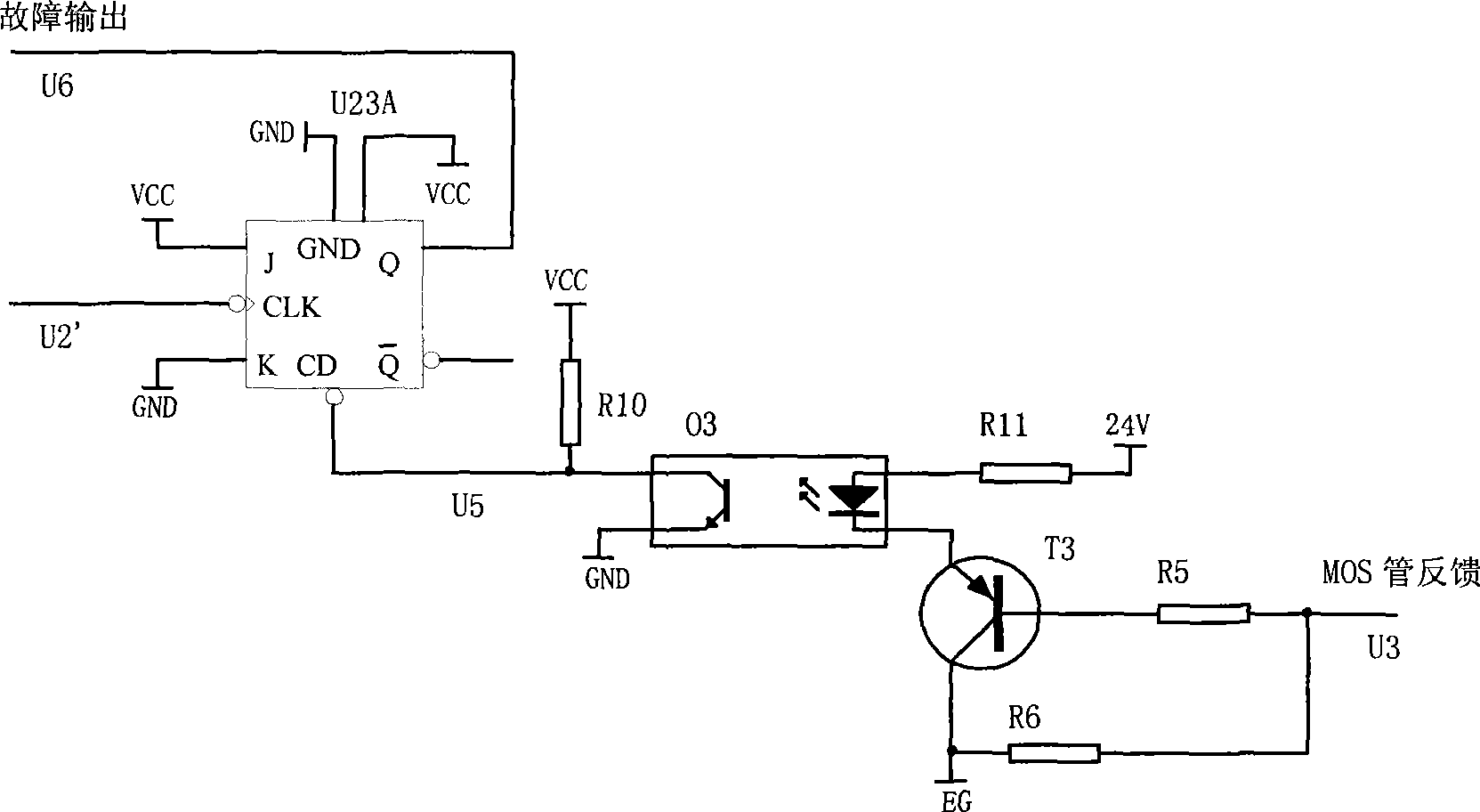
[0014] An isolated power drive circuit includes a power drive with photoelectric isolation and a fault feedback with photoelectric isolation, and also includes an isolated drive and protection circuit and an isolated fault diagnosis circuit.

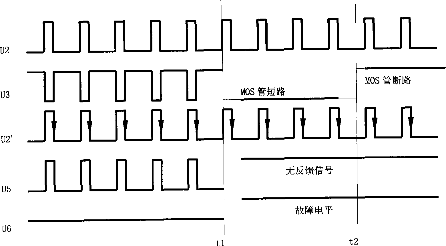
[0015] Such as Figure 4 As shown, the output protection signal drives the relay through the photoelectric device 1, supplies power to the electromagnet under normal conditions, and cuts off the power supply to the electromagnet when a fault occurs; the power drive signal drives the MOS tube through the photoelectric device 2 and the current limiting resistor 1, and controls the MOS The tube is turned on and off to provide different average driving currents to the electromagnet; the high and low level signals at the upper end of the MOS are fed back through the current limiting resistor 2 to drive the ...


PUM


Abstract

The invention belongs to the technical field of electronic control of engines and in particular relates to an isolation type power driving circuit which comprises power driving with photoelectric isolation, failure feedback with photoelectric isolation, an isolation driving and protective circuit and an isolation failure diagnosis circuit. An output protective signal drives a relay through a photoelectric apparatus 1 to supply power to an electromagnet and cuts off the power supply for the electromagnet when failure occurs; a power driving signal drives an MOS tube through a photoelectric apparatus 2 and a current-limiting resistor 1 and provides different average driving current for the electromagnet through controlling the connection and the disconnection of the MOS tube; high-level and low-level signals at the upper end of the MOS tube drive a photoelectric apparatus 3 through the feedback of a current-limiting resistor 2; a signal after the photoelectric apparatus 3 and a power driving signal form a failure distinguish logic through a J trigger and a K trigger to output a low-level signal or a high-level signal. The invention has simple structure and reliable function and effectively solves the difficult problems of electromagnetic compatibility and isolation high-power driving of an engine electric control system.

Description

technical field [0001] The invention belongs to the technical field of engine electronic control, and in particular relates to an isolated power drive circuit. Background technique [0002] In the position-type electronic control system, the gear rod of the in-line pump needs to be driven by a linear electromagnet in the form of a solenoid. The power drive of the linear electromagnet is the key technology of the electronic control system. Whether the system circuit can perform effective pulse width modulation, Accomplishing precise control of the solenoid drive circuit is one of the key factors for the success of the system. The traditional driving method is generally completed by using MOS tubes, but the system has no self-diagnosis function for MOS tubes. When the external actuator is short-circuited, it will cause the power device of the system to burn out, and other devices will have a chain reaction of damage. The most commonly used method is to connect a fuse in serie...

Claims


Application Information

Patent Timeline
IPC IPC(8): F02D41/30F02D41/22
Inventor 褚全红白思春孟长江王孝范燕朝智海峰贾利
Owner CHINA NORTH IND GRP NO 70 RES INST
Why Eureka
Try Eureka