

Method and device for detecting corrosion of component with permeability magnetic material protective layer
A corrosion detection and protective layer technology, applied in the field of non-destructive testing based on pulsed eddy current, can solve the problem of low sensitivity and achieve the effect of increasing penetration depth, improving detection sensitivity and reducing magnetic permeability
- Summary
- Abstract
- Description
- Claims
- Application Information
AI Technical Summary
Problems solved by technology
Method used
Image

Examples
Embodiment Construction
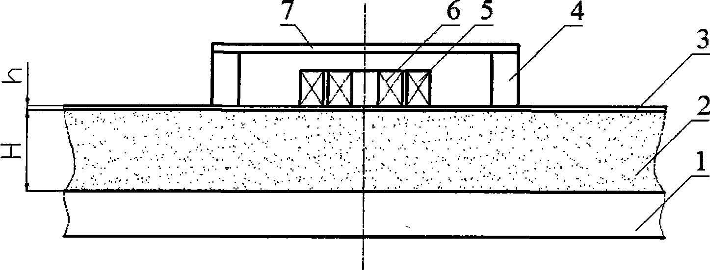
[0029] The principle schematic diagram of detection method of the present invention is as figure 1 As shown, the component under test 1 is covered with a cladding layer 2 with a thickness H, and the cladding layer 2 is covered with a magnetically permeable protective layer 3 with a thickness h. The upper end of the permanent magnet 4 is adsorbed on the left and right ends of the yoke 7, and the polarities of the magnets at both ends are perpendicular to the measured member 1 and opposite, and the lower end of the permanent magnet 4 is adsorbed (or lifted away from a certain distance) on the magnetic conductive protective layer 3, and the permanent magnet 4 , The magnetic yoke 7 and the magnetically conductive protective layer 3 form a closed magnetic path, which magnetizes the magnetically conductive protective layer 3 to deep saturation or deep saturation, reduces the magnetic permeability of the magnetically conductive protective layer material, and improves the penetration d...
PUM
 Abstract
Description
Claims
Application Information