

Shell low-pressure rotary compressor
A rotary compressor and compressor technology, applied in the field of rotary compressors, can solve problems such as insufficient oil supply, reduced efficiency of rotary compressors, and difficulty in lubricating sealed sliding vane chambers
- Summary
- Abstract
- Description
- Claims
- Application Information
AI Technical Summary
Problems solved by technology
Method used
Image

Examples
no. 1 example
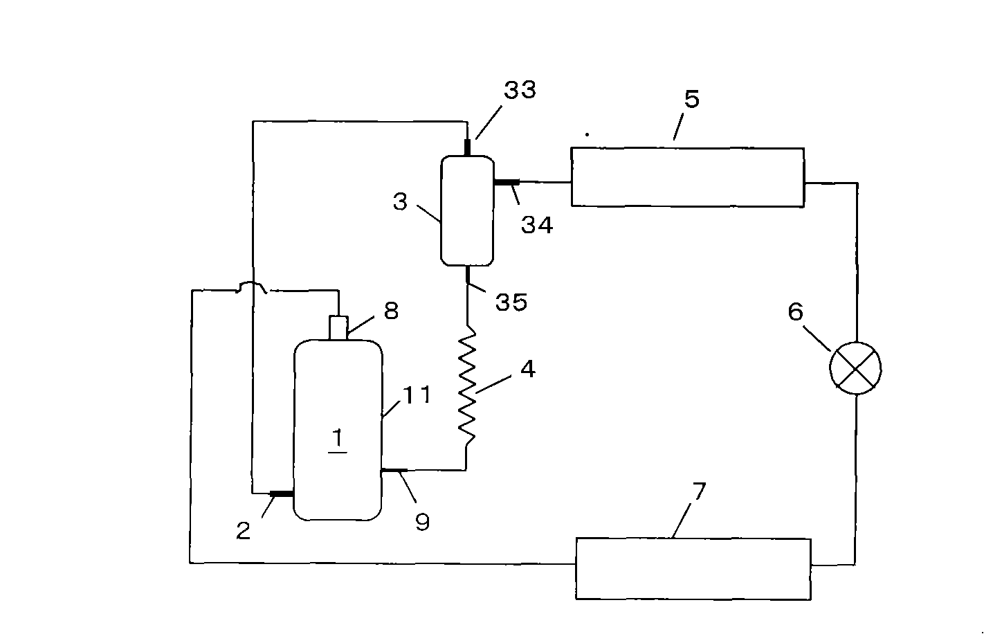
[0024] see figure 1 , shows an example of the system configuration and compressor arrangement equipped with the shell low-pressure rotary compressor 1 of the present invention, and this system corresponds to an air conditioner, a refrigerator, or a water heater. The internal pressure of the shell of the compressor 1 is the same as the suction pressure of the compressor or the low pressure side of the system.
[0025] The high-pressure refrigerant gas compressed by the compressor 1 flows into the gas inlet pipe 33 arranged on the upper part of the oil separator 3 from the exhaust pipe 2 arranged on the side of the casing 11 , and flows into the condenser 5 from the gas outlet pipe 34 . The refrigerant condensed by the condenser 5 flows from the expansion valve 6 into the evaporator 7 to be evaporated and becomes a low-pressure refrigerant gas. The low-pressure refrigerant gas is sucked into the casing 11 through the suction pipe 8 installed on the top of the casing 11 . The o...
no. 2 example
[0058] In the second embodiment, regarding the means of supplying oil to the cylinder compression chamber 25, the first oil injection hole 48a and its related schemes in the first embodiment are used, and the description is omitted here. The following third and fourth embodiments Examples are similarly omitted.
[0059] Such as Figure 5 As shown, one end of the vane chamber oil supply pipe 49 provided on the housing 11 is opened in the vane chamber 31, and the other end communicates with the oil outlet pipe 35 of the oil separator 3, that is, the oil recovery pipe 9 and the vane The cavity oil supply pipe 49 communicates through the oil outlet pipe 35 .
[0060] The oil separated by the oil separator 3 and stored at the bottom can return to the housing 11 and the vane chamber 31 of the compressor 1 from the oil recovery pipe 9 and the vane chamber oil supply pipe 49 respectively.
[0061] Since the pressure in the sealed vane chamber 31 is the pressure on the same high-pres...
no. 3 example
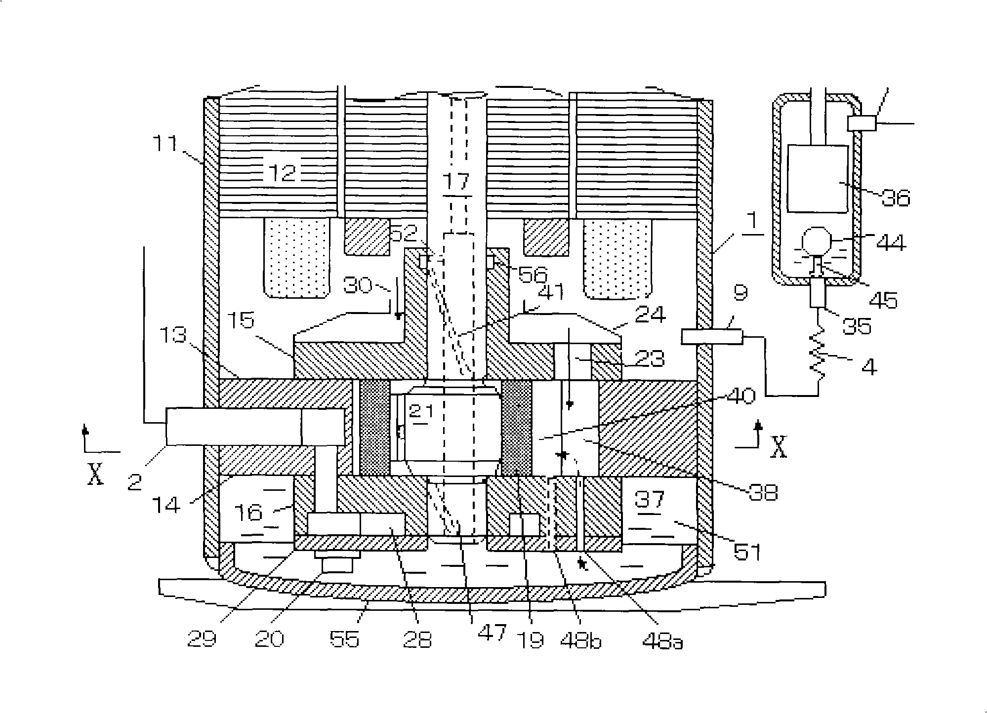
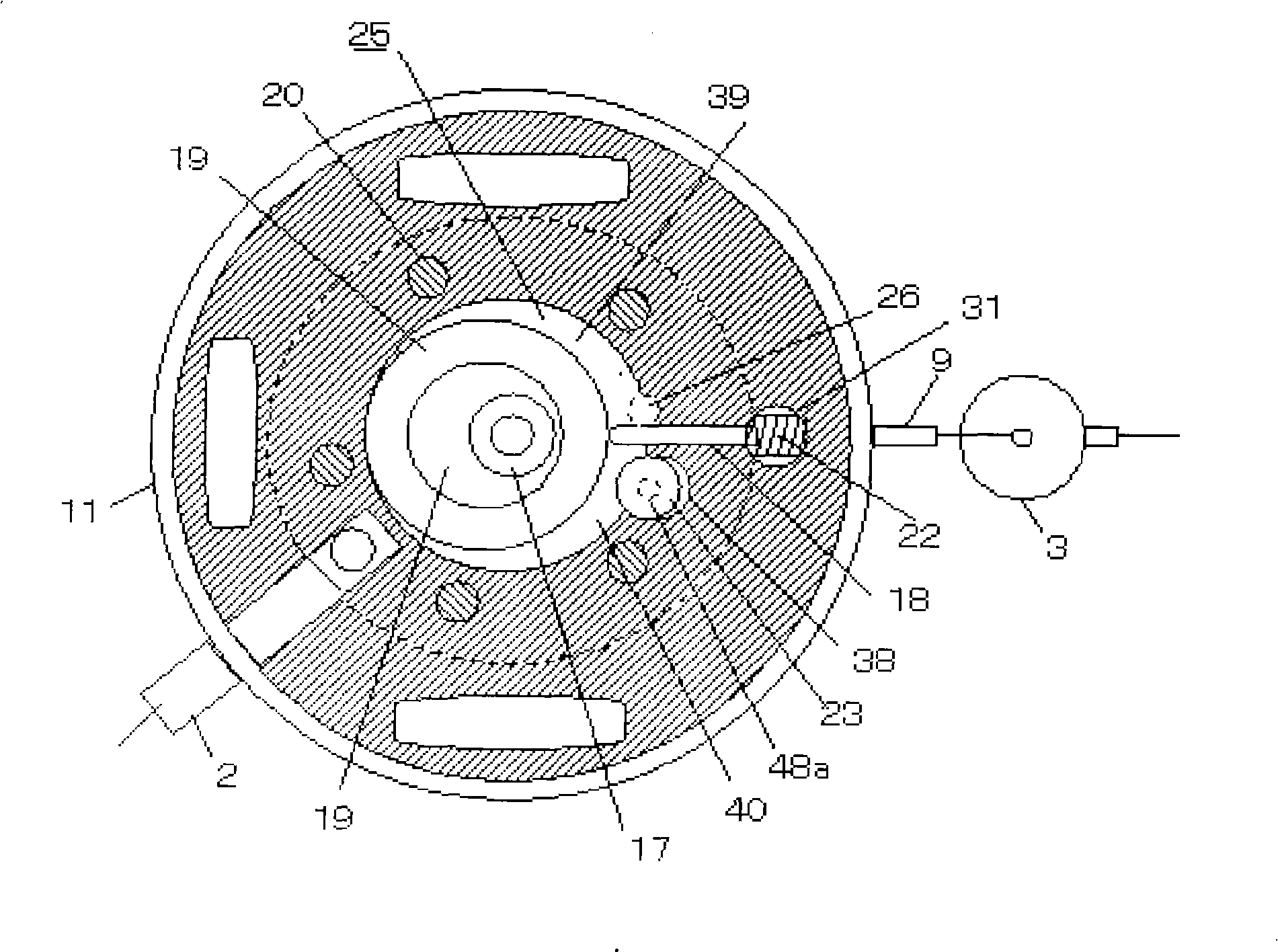
[0072] see Figure 6 and Figure 7 , the main shaft oil supply pipe 53 is arranged on the side wall of the housing 11, one end of the main shaft oil supply pipe communicates with the oil outlet pipe 35 of the oil separator 3, and the other end communicates with the main bearing 15. There is a spray hole 54 opening in the high-pressure chamber 39 of the cylinder, and the spray hole 54 is opened and closed by the upper moving surface of the piston 19 through the revolution movement of the piston 19 . Oil from the oil separator 3 on the high pressure side is injected into the liquid injection hole 54 through the main shaft oil supply pipe 53 . At this time, because the liquid injection hole 54 is opened and closed by the upper end moving surface of the piston 19, oil is intermittently injected into the high-pressure chamber 39 of the cylinder. As a result, the housing controls the amount of oil supplied.
[0073] In this embodiment, by directly supplying oil to the high-pressu...
PUM
 Abstract
Description
Claims
Application Information