Gas-magnet mixing suspended planar motor with easily expanded horizontal stroke

A gas-magnetic hybrid and planar motor technology, which is applied in the direction of synchronous machines, electrical components, electromechanical devices, etc., can solve the problems of affecting the positioning accuracy of planar motors, the lack of dynamic adjustment of air flotation air gap, and the high cost of superconducting suspension. The effect of low difficulty, reduced mass and stable output

Inactive Publication Date: 2009-09-09
SOUTHEAST UNIV
View PDF0 Cites 21 Cited by
  • Summary
  • Abstract
  • Description
  • Claims
  • Application Information

AI Technical Summary

Problems solved by technology

At present, there are mainly four types of levitation technologies that can be selected: electric levitation, superconducting levitation, gas levitation, and magnetic levitation. Among them: electric levitation realized by eddy current phenomenon will affect the positioning accuracy of planar motor due to excessive heat dissipation; superconducting levitation It is expensive and complicated to implement under the current technical conditions; the gas suspension is simple to implement and the stiffness is ideal, but the working principle of the gas suspension determines that it can only be used to set the nominal suspension position, and there is no dynamic adjustment of the air suspension air gap. The size of the technology; the positioning accuracy of the magnetic suspension bearing is mainly determined by the accuracy of the air gap sensor, which has lower requirements on the accuracy of the bearing surface, and can realize the rapid adjustment of the suspension air gap, but generally needs to add several groups of electromagnets for magnetic suspension electromagnetic execution device

Method used


Image

  • Gas-magnet mixing suspended planar motor with easily expanded horizontal stroke
  • Gas-magnet mixing suspended planar motor with easily expanded horizontal stroke
  • Gas-magnet mixing suspended planar motor with easily expanded horizontal stroke

Examples


Embodiment Construction

[0041] The structural principle and working principle of the present invention will be described in detail below in conjunction with the accompanying drawings.

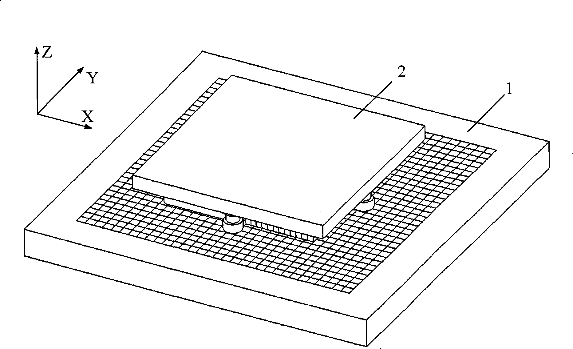
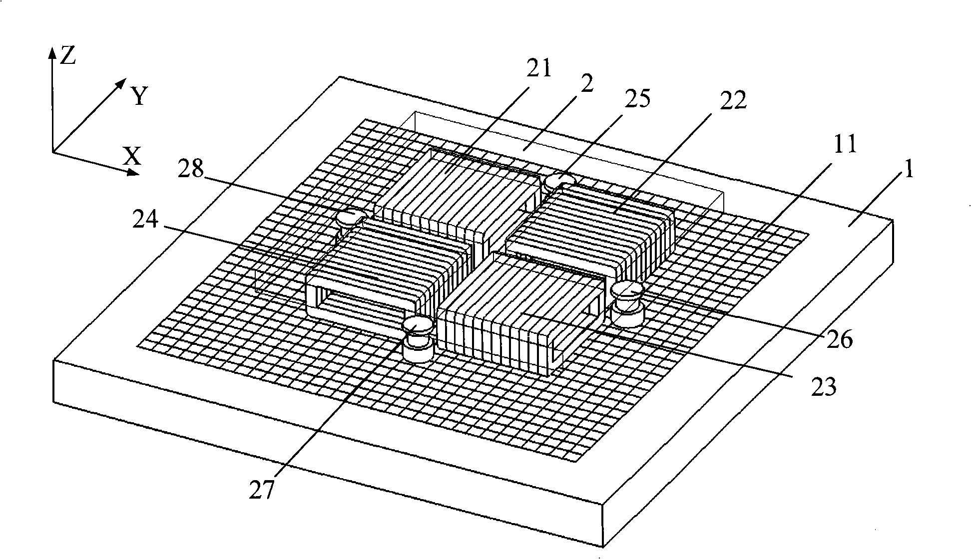
[0042] see figure 2 , image 3 , the present invention adopts a single mover structure in which the mover platform is a single-layer structure, including a stator base 1 placed along the horizontal XY plane and a mover base 2 floating on the stator base 1 and parallel to the stator base 1; The surface is embedded with a two-degree-of-freedom Halbach permanent magnet array 11 along the X-axis and Y-axis in the wavelength direction; the four corners of the lower surface of the mover substrate 2 are respectively provided with a first thrust winding 21, a second thrust winding 22, and a third thrust winding 21. Thrust winding 23, fourth thrust winding 24, wherein the wavelength directions of the first thrust winding 21 and the third thrust winding 23 are in the same direction as the X axis, and the wavelength directions...


PUM


Abstract

The invention relates to a gas-magnet mixing suspended planar motor with easily expanded horizontal stroke, comprising a stator basal body arranged along a horizontal XY plane and a mover basal body suspended on the stator basal body and is parallel with the stator basal body. Two degrees of freedom Halbach permanent magnet arrays with wavelengths along the axis X and the axis Y directions are embedded on the surface of the stator basal body; each pair of magnetic poles of the two degrees of freedom Halbach permanent magnet arrays are formed by arraying first magnet to sixth magnet according to a four* four matrix; four corners of the lower surface of the mover basal body are respectively provided with a first thrust winding, a second thrust winding, a third thrust winding and a fourth thrust winding, wherein the wavelength direction of the first thrust winding and the third thrust winding are in the axis X direction; the wavelength direction of the second thrust winding and the fourth thrust winding are in the axis Y direction; four sides of the lower surface of the mover basal body are respectively provided with a first aerostatic bearing air-cushion, a second aerostatic bearing air-cushion, a third aerostatic bearing air-cushion and a fourth aerostatic bearing air-cushion.

Description

1. Technical field: [0001] The invention relates to a planar motor that can be used in the fields of semiconductor processing industry, high-precision plotter, etc., and in particular to a gas-magnetic hybrid levitation planar motor with a single mover structure whose horizontal stroke is easy to expand. 2. Background technology: [0002] With the rapid development of advanced manufacturing industry, high-precision positioning platform technology has been in-depth research and development, and has broad application prospects in the semiconductor industry, micro-stereolithography, nano-workbench, high-precision plotter and other fields, among which the most important Its application is a high-precision lithography positioning platform in the semiconductor industry. The lithography positioning platform needs to perform precise motion control in an approximately flat space (so it is called a planar motor), including: realizing large-stroke motion in the horizontal X-axis and Y-...

Claims


Application Information

Patent Timeline
Patent Type & Authority Applications(China)
IPC IPC(8): H02K21/00H02N15/00
Inventor 周赣黄学良张前黄莉周勤博傅萌
Owner SOUTHEAST UNIV
Why Eureka
Try Eureka