
Rotary compressor and refrigeration cycle device

A technology of rotary compressors and compression mechanisms, which is applied in the direction of rotary piston machines, rotary piston pumps, components of pumping devices for elastic fluids, etc., and can solve the problem that the natural frequency of the rotor and the main shaft system cannot be fully improved, and the natural frequency of the main shaft system cannot be fully improved. Problems such as reducing the height of the compressor, and the space is similar to a closed space

Inactive Publication Date: 2009-09-09
TOSHIBA CARRIER CORP
View PDF2 Cites 8 Cited by
  • Summary
  • Abstract
  • Description
  • Claims
  • Application Information

AI Technical Summary

Problems solved by technology

[0007] However, in the structure described in Japanese Patent Application Laid-Open No. 2002-371962, the valve cover cannot be sufficiently inserted into the coil end of the stator or the inner circumference of the bobbin as an insulating member, so that the rotor and the compression mechanism cannot be brought close together.
Therefore, the natural frequency of the rotor and the main shaft system cannot be sufficiently increased, the vibration of the rotor increases during compressor operation, electromagnetic noise and vibration cannot be sufficiently suppressed, and the overall height of the compressor cannot be sufficiently reduced
[0008] In addition, although the structure described in Japanese Patent Laid-Open No. 2001-263239 can reduce electromagnetic noise and reduce the overall height of the compressor, the upper surface of the valve cover, the lower surface of the rotor, the coil ends of the stator, or the The space surrounded by the bobbin is similar to a closed space
Therefore, the resonance noise increases, and finally there is still a problem that the noise cannot be reduced

Method used


Image

  • Rotary compressor and refrigeration cycle device
  • Rotary compressor and refrigeration cycle device
  • Rotary compressor and refrigeration cycle device

Examples


Embodiment Construction

[0018] Hereinafter, embodiments of the present invention will be described with reference to the drawings.

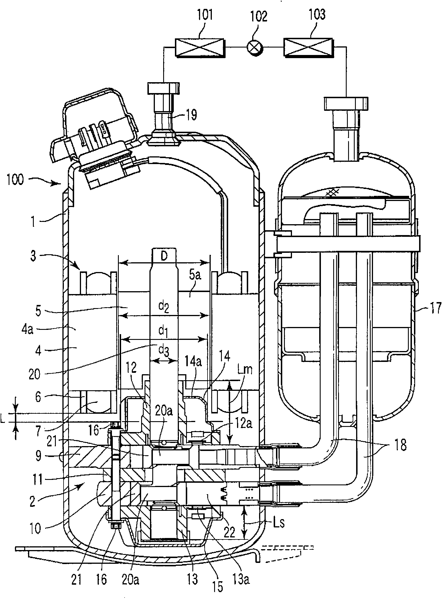
[0019] figure 1 It is a figure which shows the refrigeration cycle apparatus which concerns on one Embodiment of this invention.

[0020] In this refrigeration cycle device, a condenser 101 , an expansion device 102 , and an evaporator 103 are sequentially connected to a vertical rotary compressor 100 through refrigerant pipes.

[0021] The vertical rotary compressor 100 includes a hermetic casing 1 in which a rotary compression mechanism part 2 and a motor part 3 driving the compression mechanism part 2 via a main shaft 20 as a rotating shaft are housed vertically in an airtight state.

[0022] The compression mechanism part 2 includes: a first cylinder 9 and a second cylinder 10 arranged up and down through an intermediate partition plate 11; Main bearing 12 and auxiliary bearing 13. In each compression chamber formed in the first cylinder 9 and the second cylinder...


PUM


Abstract

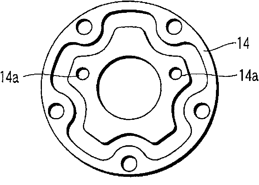
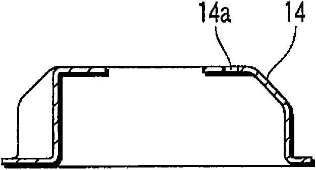
A rotary compressor is provided with a hermetic case (1); a motor section (3) arranged in the hermetic case (1); a compression mechanism section (2) driven by the motor section (3) through a main shaft (20) to eject a compressed gas from an ejection valve (12a) facing the motor section (3); and an upper valve cover (14) fixed to the compression mechanism section (2) with a bolt (16) to cover the ejection valve (12a). The motor section (3) and the compression mechanism section (2) are arranged to face each other with an interval of 2-8mm between the motor section (3) and the bolt (16) of the upper valve cover (14).

Description

technical field [0001] The present invention relates to, for example, a rotary compressor and a refrigeration cycle device constituting a refrigeration cycle circuit of an air conditioner or the like. Background technique [0002] In general, a rotary compressor used in a refrigeration cycle such as an air conditioner includes a compression mechanism for compressing fluid and a motor that drives the compression mechanism through a main shaft (rotary shaft) in a hermetically sealed casing. [0003] Conventionally, in this type of rotary compressor, there has been a problem of increased electromagnetic noise in the motor unit due to the concentrated winding of the stator constituting the motor unit and the use of rare earth permanent magnets in the rotor. In particular, when the natural frequency of the rotor / spindle system becomes an integral multiple of the operating frequency of the compressor, there is a problem that the vibration of the rotor increases and electromagnetic...

Claims


Application Information

Patent Timeline
IPC IPC(8): F04C29/12F04C29/06
CPCF04C23/008F04C23/001F04C18/30
Inventor 高岛和志田胜吾北市昌一郎小野田泉
Owner TOSHIBA CARRIER CORP
Learn More