A boring machine

The technology of a boring machine and a boring tool holder is applied in the field of boring machines to achieve the effects of high precision, reduced labor intensity, and good controllable performance of boring.

Active Publication Date: 2009-09-16
WUCHANG SHIPBUILDING IND
View PDF0 Cites 12 Cited by
  • Summary
  • Abstract
  • Description
  • Claims
  • Application Information

AI Technical Summary

Problems solved by technology

In addition, it must also have the function of milling the end face of the flange hole
Existing boring machines cannot meet the above requirements

Method used


Image

  • A boring machine
  • A boring machine
  • A boring machine

Examples


Embodiment Construction

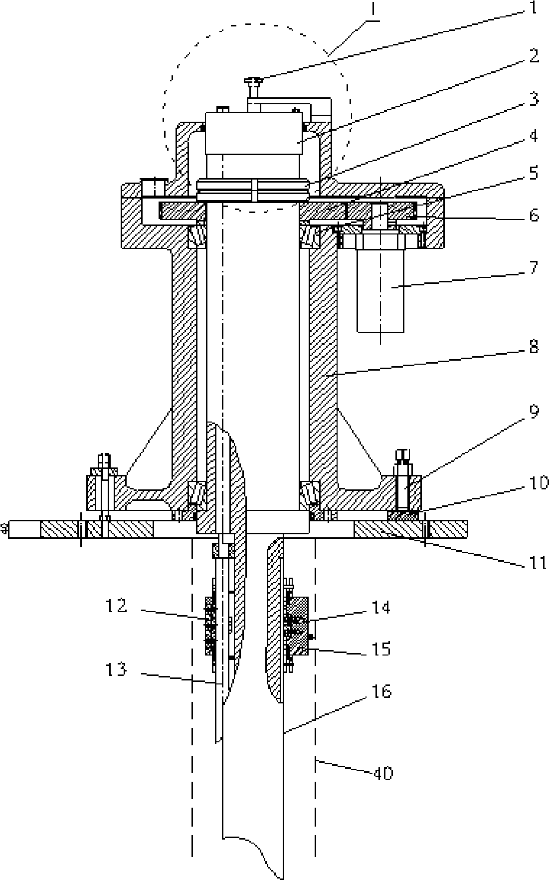
[0016] The boring machine of this specific embodiment is designed and manufactured for the boring process on the shipbuilding site. It needs to bore holes with a depth of Φ220-Φ340mm and a depth of 1500mm and an end face of Φ200-Φ500mm. The xxx ship stern rudder is made of MACR special steel with high strength and hardness. Large, general equipment can not be processed, and can not meet the technical requirements, hole cylindricity ≤ 0.03mm, verticality between the end face and the hole center line ≤ 0.03mm, surface roughness of the boring ≤ 3.2.

[0017] Such as figure 1 As shown, the stepless speed regulating machine 7 is driven by the hydraulic station, the stepless speed regulating machine 7 is connected with the driving gear 6 , and the driving gear 6 is connected with the driven gear 4 . The boring bar 16 is installed in the shell 8 through the round nut 3 located in the shell 8 and the E-class conical liquid subbearing. The shell 8 is fixedly connected with the ship pla...


PUM


Abstract

The invention relates to a field processing boring machine, which includes a hydraulic station, a variable speed machine, a boring bar, a feed screw, a boring knife rack, and a blade, which is characterized in that the top surface of the boring bar is mounted with a gear shifting box, the feed screw is axially mounted in the boring bar adjacent to the boring bar external diameter, the upper end of the feed screw is connected to the gear shifting box; the boring knife rack is mounted on the boring bar through a first Huff cramping apparatus, the lower end of the feed screw is connected to feed screw nuts, the feed screw nuts are connected to the first Huff cramping apparatus, the boring bar is provided with knife rack guides, the knife rack guides are mounted with navigation keys, the navigation keys are connected to the boring knife rack. The present invention solves the field quickly boring big, deep hole problem in industry field, and has good boring controllable performance and high accuracy; also simultaneously integrates the milling function to the flange end-face and has electric and manual switch operation schema, has good operating performance, reduces labor intensity and improves its operating efficiency.

Description

technical field [0001] The invention relates to a boring machine, in particular to a boring machine for on-site processing. Background technique [0002] In shipbuilding, it is necessary to carry out on-site boring for the flange hole of the ship stern rudder shaft, and this kind of hole has the characteristics of large hole diameter and deep boring. In addition, it must also have the function of milling the end face of the flange hole. Existing boring machines cannot meet the above requirements. Contents of the invention [0003] The technical problem to be solved by the present invention is to provide a boring machine with a unique structure, which can be used for large-diameter and deep-boring processing on the processing site. [0004] In order to solve the above technical problems, the boring machine provided by the present invention includes a hydraulic station, a stepless speed regulator, a boring bar, a feed screw, a boring tool holder, and a cutter head. The hyd...

Claims


Application Information

Patent Timeline
Patent Type & Authority Applications(China)
IPC IPC(8): B23B41/02B23B47/18B23B47/14B23P23/00B23Q5/04B23Q5/34
Inventor 高宏庞光明闫朝勤李胜新王立洲
Owner WUCHANG SHIPBUILDING IND
Why Eureka
Try Eureka