Wind power generation chimney

A technology of generators and round tubes, which is applied in wind power generation, wind power engines, wind power motor combinations, etc., can solve problems such as insufficiency, and achieve the effect of large moment of inertia

Inactive Publication Date: 2009-09-16
刘新广
View PDF0 Cites 10 Cited by
  • Summary
  • Abstract
  • Description
  • Claims
  • Application Information

AI Technical Summary

Problems solved by technology

In order to improve the efficiency of power generation, various wind rotors and generators and their combinations have been developed, but they are not enough.

Method used


Image

  • Wind power generation chimney
  • Wind power generation chimney
  • Wind power generation chimney

Examples


Embodiment 1

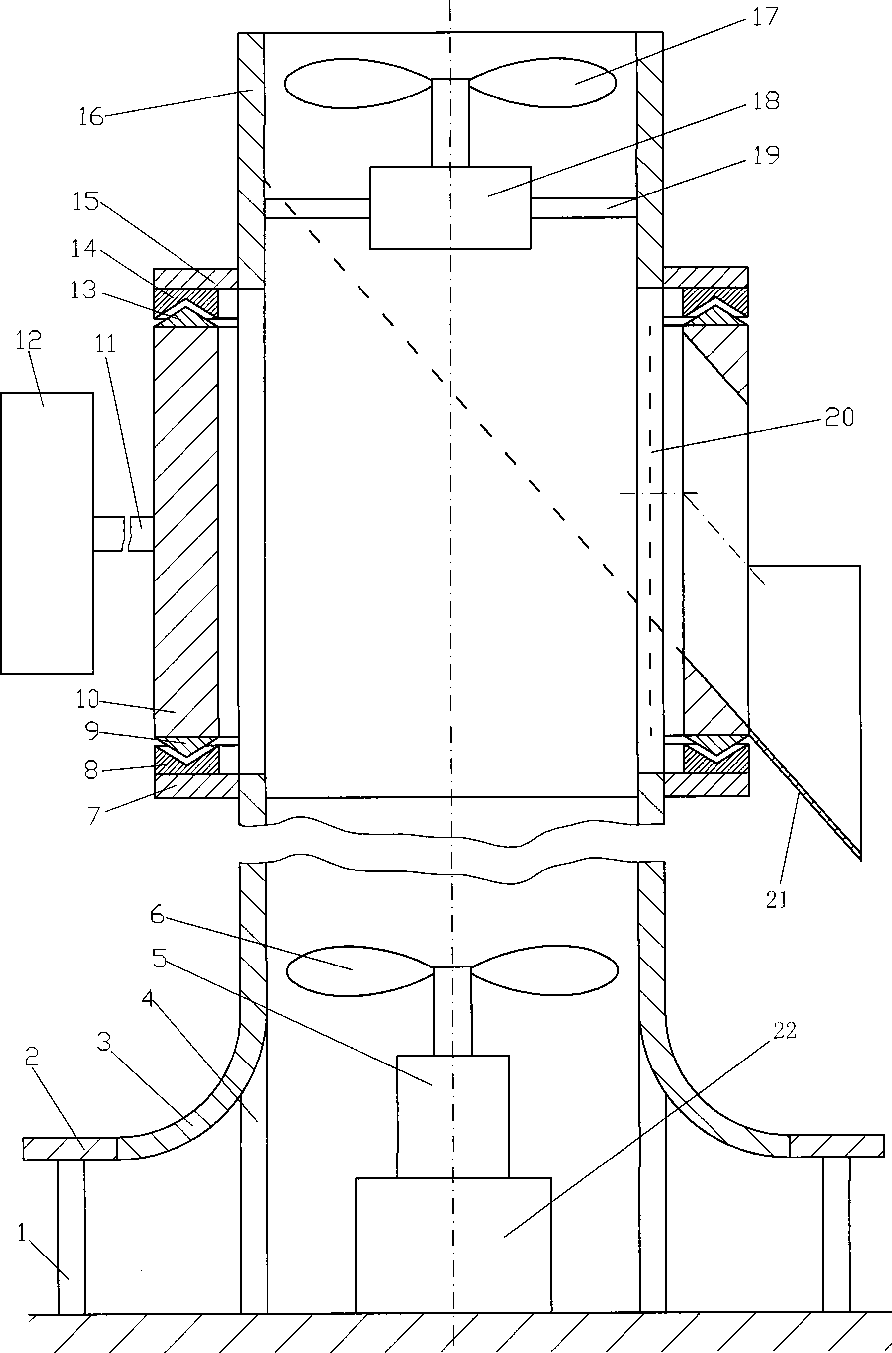
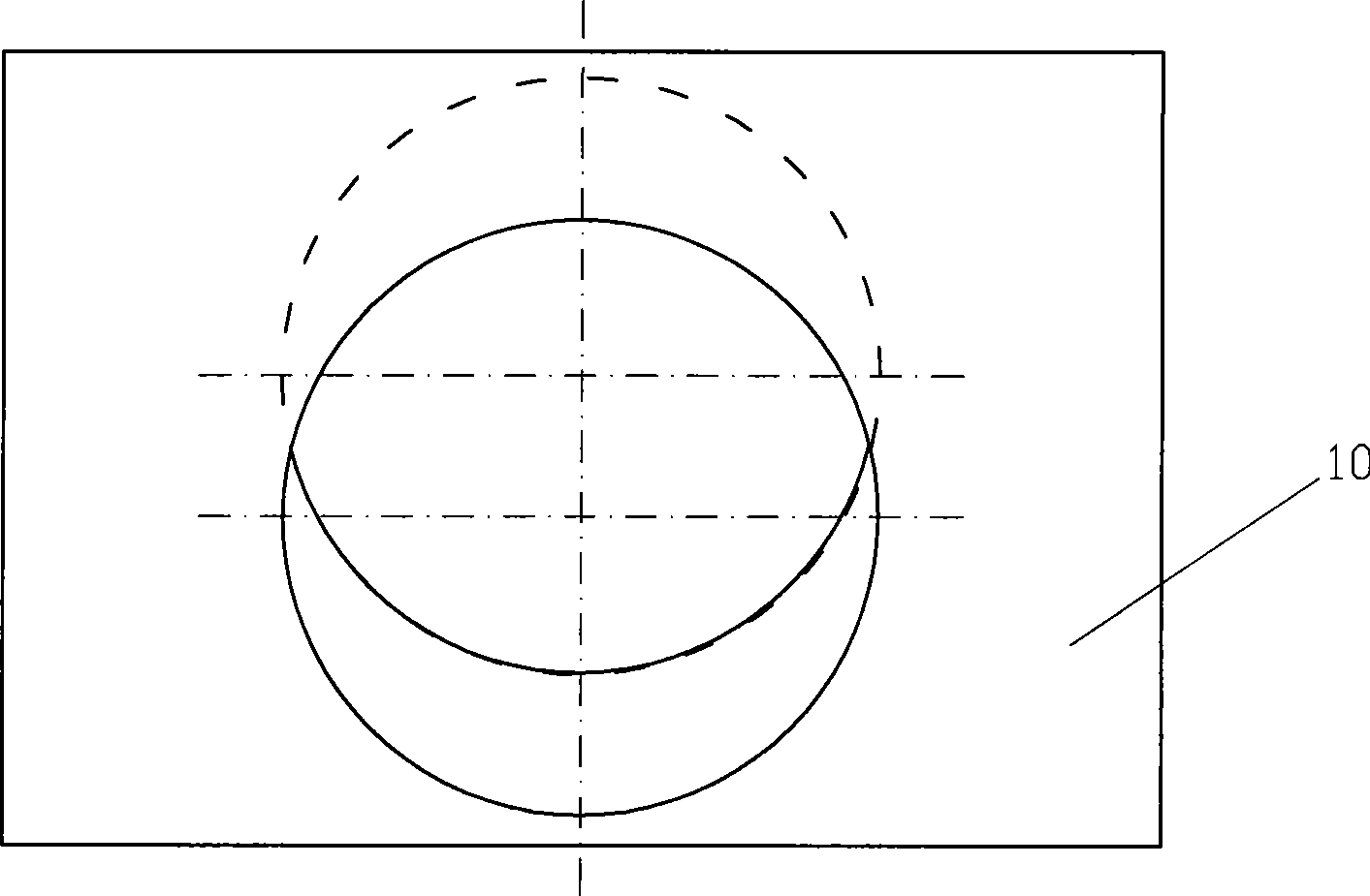
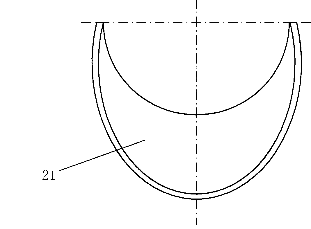
[0023] Embodiment one: if Figure 1 to Figure 3 Show. The pipe diameter of the vertical circular pipe 3 is made to be the same size up and down or made to be small at the top and large at the bottom. The vertical circular pipe 3 is connected and supported by several columns 4 fixed on the foundation; the circular heat collecting plate or current collecting plate 2 is composed of several A column 1 fixed on the foundation is connected and supported, and is sleeved on the lower edge of the vertical circular tube 3. The circular heat collecting plate is made of transparent material, allowing sunlight to transmit and heat the air below. The circular collecting plate is used Made of other materials to collect hot air; the circle 7 is sleeved on the outer circle of the upper end of the vertical pipe 3, the circle 15 is sleeved on the outer circle of the lower end of the vertical pipe 16, and the upper end of the circle 7 is consolidated into a V-ring groove shaped along the vertical ...

Embodiment 2

[0024] Embodiment two: if Figure 4 Show. When wind or updraft speed is small, or it is not easy to install support 19, generator 18 and impeller 17, etc., spoke-shaped support 19, generator 18 and impeller 17 can be removed, and impeller 6 drives generator 5 to generate electricity.

Embodiment 3

[0025] Embodiment three: as Figure 5 Show, under certain circumstances, such as in order to alleviate the harm of noise, can remove pad 22, generator 5 and impeller 6, drive generator 18 to generate electricity with impeller 17.


PUM


Abstract

The invention arranges a chimney-shaped vertical round pipe on the ground surface; the lower end of the vertical round pipe is provided with an outer hat brim-shaped edge; the vertical round pipe leaves the ground surface by a distance; the upper end of the vertical round pipe is provided with a trough-shaped permanent magnetic ring with a V-shaped ring; a round pipe is prepared; wherein the upper end and the lower end of the round pipe are fixedly connected with a conical magnetic ring respectively, and the side part of the round pipe is provided with an air inlet hole which is inclined upwards from exterior to interior; the other side of the round pipe right facing to the inclined hole is provided with a wind direction rudder; subsequently, the round pipe is vertically arranged in the trough-shaped permanent magnetic ring with the V-shaped ring at the upper end of the vertical round pipe, with a gap and the same polarity face to each other; subsequently, a vertical round pipe with a inverted V-ring trough-shaped permanent magnetic ring is prepared and arranged above the round pipe with the inclined hole; furthermore, the inverted V-ring trough-shaped permanent magnetic ring and the conical magnetic ring at the upper end of the round pipe face to each other with a gap and the same polarity; the vertical round pipes at the upper side and the lower side of the round pipe with the inclined hole are connected with each other by a plurality of spaced connecting rollers; an impeller and a power generator are respectively arranged at the inlet of the vertical round pipe with the edge and the outlet of the upper-most vertical round pipe; and the wind power generation chimney generates the power by the horizontal wind and updraft simultaneously, has high efficiency and is practical.

Description

technical field [0001] The invention relates to wind power generation technology, in particular to a wind power generation chimney for converging vertical updraft and horizontal wind. Background technique [0002] Wind energy is an inexhaustible source of clean energy. People love it and have designed countless wind power generation devices, which are mainly composed of wind wheels and generators. In order to improve the power generation efficiency, various wind rotors and generators and combinations thereof have been developed, but these are not enough. Contents of the invention [0003] The present invention designs a wind power generation chimney that combines vertical updraft and horizontal wind, and aims to capture wind energy to the greatest extent and fully improve the efficiency of wind power generation. [0004] The present invention is realized according to the following technical solutions. [0005] Such as Figure 1 to Figure 3 Show. The pipe diameter of the...

Claims


Application Information

Patent Timeline
Patent Type & Authority Applications(China)
IPC IPC(8): F03D1/04F03D9/00F03D9/25F03D9/37
CPCY02E10/725Y02E10/465Y02E10/46Y02E10/72Y02E10/728
Inventor 刘新广
Owner 刘新广
Why Eureka
Try Eureka