Rapid fuel gas condensation system with double-tower direct spray

A condensing system and direct technology, applied in direct contact heat exchangers, indirect heat exchangers, petroleum industry, etc., can solve the problem of insufficient condensation of condensable gases, reduce bio-oil yield, increase process difficulty and cost, etc. problems, to achieve the effect of meeting the requirements of rapid cooling, speeding up the condensation speed, and fast cooling speed

Active Publication Date: 2009-09-16
GUANGZHOU DEVOTION THERMAL TECH
View PDF1 Cites 12 Cited by
  • Summary
  • Abstract
  • Description
  • Claims
  • Application Information

AI Technical Summary

Problems solved by technology

However, as can be seen from the above description, the CN200510057215.8 patent has the following disadvantages: first, the medium used to condense the pyrolysis gas in the condenser is water, therefore, the obtained bio-oil will contain a large amount of If you want to use moisture, you need to use special equipment to further separate it, which will increase the difficulty and cost of the process; second, the condensation process is completed in one step with a condenser. On the one hand, it may cause a part of the pyrolysis gas to be condensed Insufficient condensation of gases, on the other hand, may lead to further pyrolysis of some condensable gases, thereby reducing bio-oil yield

Method used


Image

  • Rapid fuel gas condensation system with double-tower direct spray

Examples


Embodiment 1

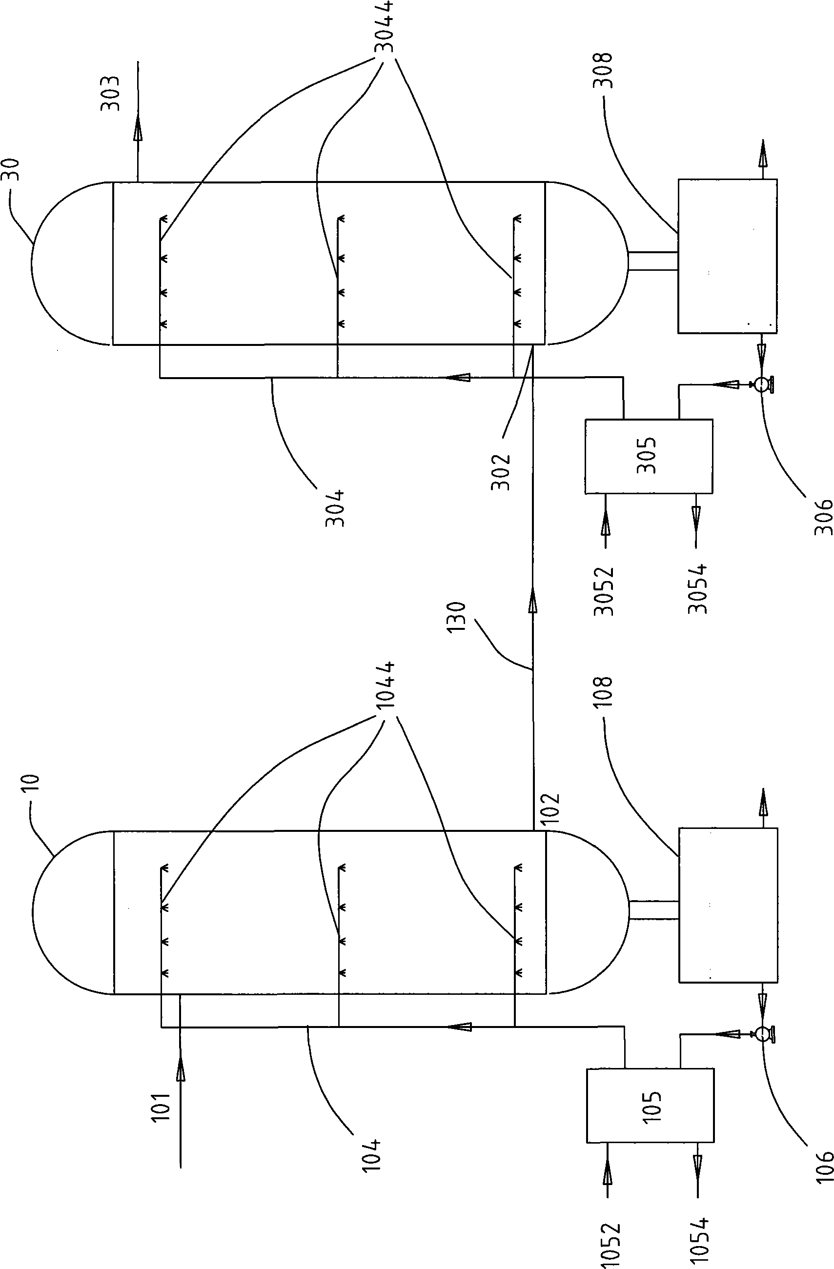
[0023] Please refer to figure 1 , the double-tower direct spray cracking gas rapid condensation system of the present invention comprises a first-stage spray tower 10 provided with a high-temperature pyrolysis gas inlet 101 and a pyrolysis gas outlet 102, a pyrolysis gas inlet 302 and a non-condensable gas The second-stage spray tower 30 of the outlet 303, the connecting pipe 130 connecting the pyrolysis gas outlet 102 of the first-stage spray tower 10 and the pyrolysis gas inlet 302 of the second-stage spray tower 30, and the first-stage spray The bio-oil storage tank 108 connected to the condensed bio-oil outlet of the tower 10, the bio-oil storage tank 308 connected to the condensed bio-oil outlet of the second-stage spray tower 30, the first atomized spraying subsystem (in this embodiment Including a first atomizing spray unit 104, a first circulating oil pump 106 connected to a first bio-oil storage tank 108, and a first heat exchange unit connected between the first circ...

Embodiment 2

[0031] As another kind of scheme of the present invention, other parts are identical with embodiment 1, and difference is:

[0032] The condensing medium used for the first atomizing spray unit 10 and the second atomizing spray unit 30 can come from outside the system, that is, the bio-oil generated by the system itself is not used, so the system can not be provided with the first heat exchanger 10 and the second heat exchanger 30.

[0033] Moreover, the high-temperature pyrolysis gas inlet 101 of the first-stage spray tower 10 is arranged below the pyrolysis gas outlet 102, that is, the first-stage spray tower also adopts a reverse spraying path with the gas.

Embodiment 3

[0035] As another kind of scheme of the present invention, other parts are identical with embodiment 1, and difference is:

[0036] Using a heat exchanger, a circulating oil pump and a bio-oil storage tank, the bio-oil produced by the first-stage spray tower 10 and the second-stage spray tower 30 all enters the same bio-oil storage tank, and part of the bio-oil is produced by the same bio-oil storage tank. A circulating oil pump is sent to the same heat exchanger for cooling and then sent to the first atomizing spray unit 104 and the second atomizing spray unit 304 respectively.


PUM


Abstract

The invention discloses a rapid fuel gas condensation system with double-tower direct spray, comprising a first stage spray tower, a second stage spray tower, a connecting pipeline communicated with the first stage spray tower and the second stage spray tower, at least one bio-oil storage tank connected with condensed bio-oil outlets of the first stage spray tower and the second stage spray tower, and at least one atomized spray sub-system. The atomized spray sub-system comprises a first atomized spray unit and a second atomized spray unit respectively arranged inside the first stage spray tower and the second stage spray tower partially and extensively. The first atomized spray unit and the second atomized spray unit respectively comprise two layers or more than two layers of spraying nozzles that are used for the atomized spray of condensed media and arranged at intervals in the height direction of the inner space of the first stage spray tower and the second stage spray tower. The system can fully inhibit the further schizolysis of condensable components and avoid the complicated process of subsequent separation caused by additional condensed media.

Description

technical field [0001] The invention relates to a bio-oil condensing device, in particular to a direct spraying quick condensing device. Background technique [0002] With the continuous development of the world economy, energy and environmental issues have become increasingly prominent. The main energy sources currently used by human beings are oil, natural gas and coal. According to the statistics of the International Energy Agency, the lifespan of these three kinds of energy for human exploitation on the earth is only 40 years, 50 years and 240 years respectively. The development of new energy has become a major issue related to the sustainable development of human society. [0003] Biomass energy is the solar energy stored in plants by the photosynthesis of plants and solar energy. It is estimated that the annual energy stored in plants is equivalent to 10 times the world's main fuel consumption, while the utilization of energy as energy is less than 1% of the total. ...

Claims


Application Information

Patent Timeline
Patent Type & Authority Applications(China)
IPC IPC(8): F28C3/08C10G1/00F28D9/00
Inventor 陈平常厚春李祖芹马革
Owner GUANGZHOU DEVOTION THERMAL TECH
Why Eureka
Try Eureka