High-speed adjustable optical comb filter

An optical comb filter, high-speed technology, applied in the coupling of optical waveguide, wavelength division multiplexing system, electromagnetic wave transmission system, etc., can solve the problems of limited application, non-adjustable central wavelength of comb filter, etc., and achieve flexibility And the effect of improving adaptability and quick adjustment

Inactive Publication Date: 2009-09-16
ZHEJIANG UNIV
View PDF0 Cites 10 Cited by
  • Summary
  • Abstract
  • Description
  • Claims
  • Application Information

AI Technical Summary

Problems solved by technology

However, the non-tunable central wavelength of the comb filter limits its application in dynamic DWDM systems to a large extent.

Method used


Image

  • High-speed adjustable optical comb filter
  • High-speed adjustable optical comb filter
  • High-speed adjustable optical comb filter

Examples


Embodiment Construction

[0016] Further illustrate the present invention below in conjunction with accompanying drawing:

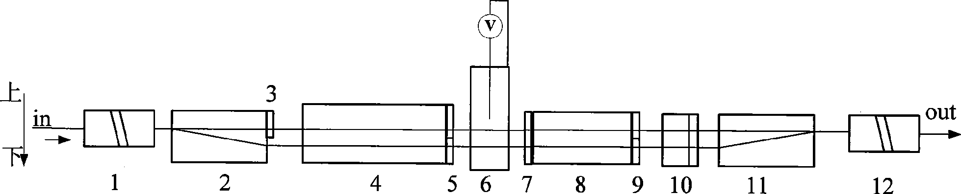
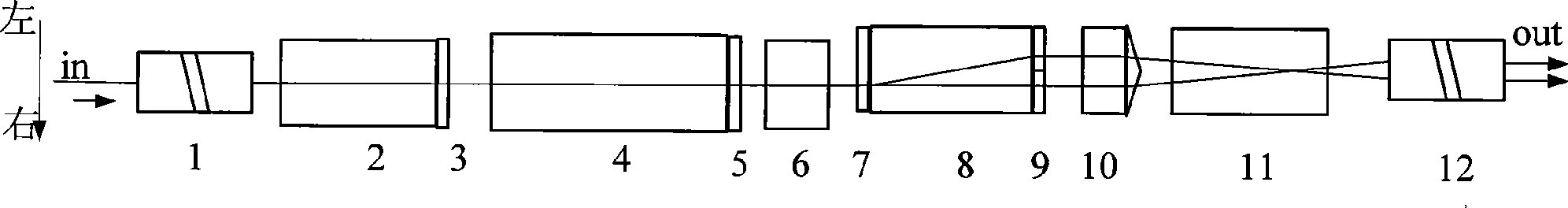
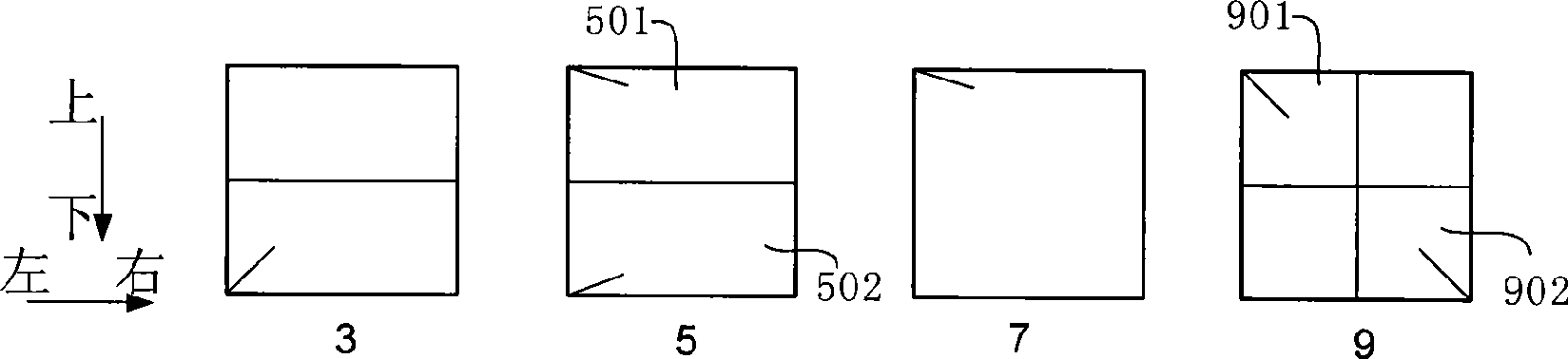
[0017] Such as figure 1 and figure 2 As shown in the figure, a high-speed tunable optical comb filter consists of a single fiber collimator 1, a first polarization-shifting crystal 2, a first half-wave plate group 3, and a birefringent retardation crystal 4 placed in sequence in the same horizontal optical path direction. , second half-wave plate group 5, electro-optic retardation plate 6, third half-wave plate group 7, second polarization-shifted crystal 8, fourth half-wave plate group 9, roof prism 10, third polarization-shifted crystal 11 and dual optical fiber Collimator 12; the parallel light beam separated by the second polarization-shifting crystal is collimated and coupled to the double-fiber collimator by the roof prism and the third polarization-shifting crystal; the center of the optical comb filter is realized by controlling the applied voltage of the electro-optical...


PUM


Abstract

The invention discloses a high-speed adjustable optical comb filter. A single optical fiber collimator, a first polarized displacement crystal, a first half wave plate cluster, a birefringent retarding crystal, a second half wave plate cluster, an electro-optical retarder, a third half wave plate cluster, a second polarized displacement crystal, a fourth half wave plate cluster, a roof prism, a third polarized displacement crystal and a double optical fiber collimator are sequentially placed in the same horizontal optical path direction; parallel beams separated by the second polarized displacement crystal are collimated and coupled to the double optical fiber collimator via the roof prism and the third polarized displacement crystal; and high-speed adjustable central wavelength of the optical comb filter can be realized by controlling the externally applied voltage of the electro-optical retarder. The invention achieves high-speed dynamic adjustability of the central wavelength of the comb filter and has the characteristics of compact structure, convenient manufacturing and stable and reliable performance.

Description

technical field [0001] The invention relates to the field of optical fiber communication, in particular to a high-speed adjustable optical comb filter. Background technique [0002] With the rapid development of optical fiber communication technology and the maturity of multimedia communication technology, people's demand for data bandwidth is increasing. The development of Dense Wavelength Division Multiplexing (DWDM) technology has greatly eased the increasing pressure of communication traffic. The optical comb filter is an excellent DWDM device. In addition to being used for wavelength division multiplexing / demultiplexing, it can also be used to upgrade the system capacity and provide more convenient conditions for the development of optical fiber communication. In addition, as an efficient wavelength selective filter, the optical comb filter can also be used in multi-wavelength lasers, photoelectric measurement systems and all-optical information processing. [0003] A...

Claims


Application Information

Patent Timeline
Patent Type & Authority Applications(China)
IPC IPC(8): G02B6/27G02B6/30G02B5/30H04B10/12H04J14/02
Inventor 章飞金晓峰冀军章献民池灏
Owner ZHEJIANG UNIV
Why Eureka
Try Eureka