Shared substrate multi-beam antenna based on eight port junctions

A multi-beam antenna and eight-port technology, applied to antennas, antenna unit combinations with different polarization directions, slot antennas, etc., can solve problems affecting common substrates, restricting beamforming network integration, large mutual coupling, and radiation , to achieve the effect of convenient integration, compact structure and close performance

Active Publication Date: 2009-09-16
SOUTHEAST UNIV
View PDF0 Cites 17 Cited by
  • Summary
  • Abstract
  • Description
  • Claims
  • Application Information

AI Technical Summary

Problems solved by technology

For example, the millimeter-wave beamforming network realized by the general planar circuit transmission line is difficult to integrate with the antenna array on the same dielectric substrate, mainly because the circuit will generate great mutual coupling and radiation when operating at such a high frequency, which will be extremely Integration of Earth Constrained Beamforming Networks and Affecting Patterns of Common-Substrate Multibeam Antennas

Method used


Image

  • Shared substrate multi-beam antenna based on eight port junctions
  • Shared substrate multi-beam antenna based on eight port junctions

Examples


Embodiment Construction

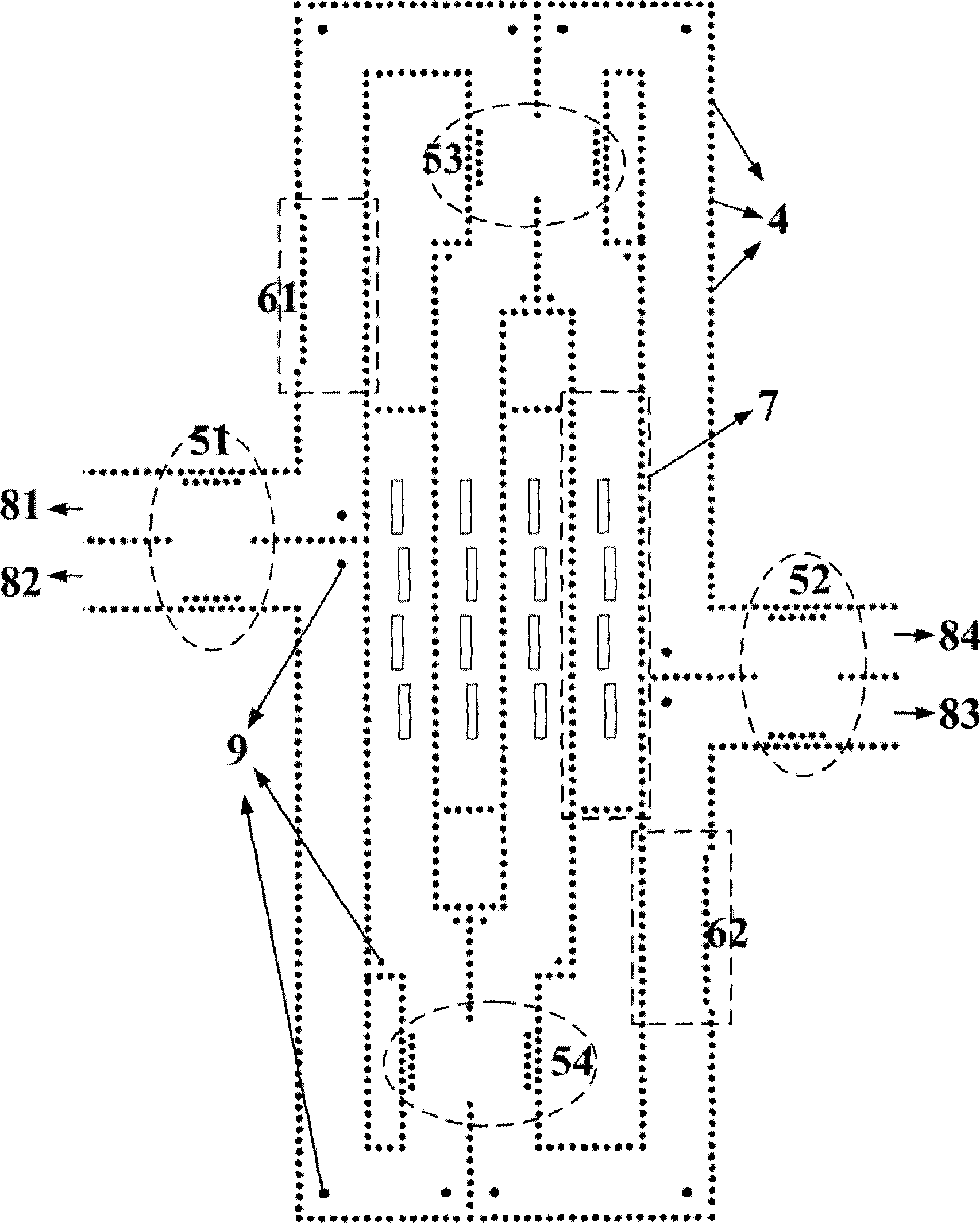
[0018]The common-substrate multi-beam antenna based on the eight-port junction in the present invention includes an upper metal copper-clad surface 1, a lower metal copper-clad surface 2, a dielectric substrate 3, a metallized through hole 4, and a substrate-integrated waveguide 90° directional coupler 51. Substrate-integrated waveguide 90° directional coupler 52. Substrate-integrated waveguide 90° directional coupler 53. Substrate-integrated waveguide 90° directional coupler 54. Substrate-integrated waveguide 45° phase shifter 61. Substrate-integrated waveguide 45° phase shifter 62, substrate-integrated waveguide 4-slot slot array antenna 7, input port 81, input port 82, input port 83, input port 84, inductive metal rod 9; upper metal-clad copper surface 1, lower-layer metal-clad copper The surface 2 is located on the upper and lower surfaces of the dielectric substrate 3, and the metallized through hole 4 passes through the dielectric substrate 3 to connect with the upper met...


PUM


Abstract

The invention relates to a shared substrate multi-beam antenna based on eight port junctions. The structure of the prior eight port junctions is provided with two fixed phase shifters of 45 degrees, and a four-port shared substrate multi-beam antenna in millimeter wave frequency is achieved by using substrate integrated waveguide. The shared substrate multi-beam antenna has the similar performance as a multi-beam antenna fed by using a 4*4Butler matrix, and has the advantages of compact volume, non-crossing transmission line structure, high reliability, radiation chrematistics uninterrupted by a beam shaping network, low manufacturing cost, easy mass production and easy integration with an active circuit. A substrate integrated waveguide antenna (7) with four groove clearances is positioned above an upper metal copper-clad surface (1) and consists of four groove clearance units, and the groove clearance units positioned at two sides of a center line are provided with groove clearances respectively so as to form four unit antenna arrays.

Description

technical field [0001] The common-substrate multi-beam antenna based on eight-port junction is suitable for microwave and millimeter-wave mobile communications, satellite communications, radar detection, space power synthesis, microwave imaging, and smart antennas. Background technique [0002] The rapid development of mobile communication makes the traditional multiple access methods, such as CDMA, FDMA, TDMA, etc., unable to meet the growing needs of capacity expansion. The multi-beam antenna generates multiple beams with different directions through the beamforming network to cover the entire user area, so as to achieve the goals of increasing channel capacity, reducing interference, and reducing transmission power consumption. Beamforming networks can generally be divided into two categories: circuits (also known as networks) and quasi-optical lenses. Among them, the circuit type is formed by connecting power dividers and couplers through transmission lines. The phase ...

Claims


Application Information

Patent Timeline
Patent Type & Authority Applications(China)
IPC IPC(8): H01Q13/18H01Q21/24H01Q3/34
Inventor 洪伟程钰间吴柯
Owner SOUTHEAST UNIV
Why Eureka
Try Eureka