
Amorphous alloy and preparation method thereof

A technology for ingot casting of amorphous alloys and master alloys, which is applied in the fields of high toughness and easy-to-prepare amorphous alloys and their preparation and high strength. It can solve the problems of high preparation conditions, low strength, and low toughness, and achieve raw materials Reduced requirements for purity and vacuum, good amorphous-forming ability, and improved strength and toughness

Active Publication Date: 2009-09-23
BYD CO LTD
View PDF0 Cites 9 Cited by
  • Summary
  • Abstract
  • Description
  • Claims
  • Application Information

AI Technical Summary

Problems solved by technology

[0004] The purpose of the present invention is to overcome the defects of low toughness, low strength and high requirements for preparation conditions of existing copper-zirconium-based amorphous alloys, thereby providing an amorphous alloy with high strength and high toughness and extremely low requirements for preparation conditions

Method used


Image

  • Amorphous alloy and preparation method thereof

Examples


preparation example Construction

[0017] The invention provides a method for preparing an amorphous alloy, the method comprising the following steps: a method for preparing an amorphous alloy, the method comprising the steps of:

[0018] 1), batching: take Cu, Zr, M and Be according to Cu:Zr:M:Be=a:b:c:d and carry out batching;

[0019] 2) Ingot casting: Vacuumize the melting furnace to a vacuum degree of 10 -2 -10 3 Pa, the raw materials after step 1) are mixed uniformly, and smelted, with 10-10 4 Cooling at a cooling rate of K / s to obtain a master alloy ingot;

[0020] 3), forming: the master alloy ingot obtained in step 2) is melted, and the conventional forming method is used for 10-10 4 K / s cooling rate cooling molding;

[0021] Wherein, M is one or more elements among transition group metals except Cu and Zr, Al, Sn and Si. a, b, c, d are mole percentages and a+b+c+d=100; 15≤a≤45, 10≤b≤50, 5≤c≤35, 0≤d≤30, preferably 30≤a ≤45, 30≤b≤50, 5≤c≤25, 0.01≤d≤10.

[0022] The melting temperature is 1500-250...

Embodiment 1

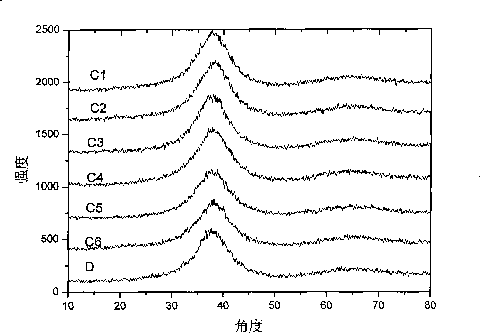
[0028] A total of 25g of Cu, Zr, Ti, Al, and Y with a purity of 99.6wt% was placed in an electric arc melting furnace according to the ratio of Cu:Zr:Ti:Al:Y=44:45:2:7:2 and evacuated to 50Pa , into the argon, under the condition of 2000 ℃ for melting, melting time 20-50s, fully stirred and then cooled into ingots, cooling speed 10 4 K / s, melted by arc heating at 2000°C and cooled at a rate of 10 4 K / s is cast into an alloy sample C1 with a size of 3*10*100mm in a beryllium copper mold.

Embodiment 2

[0030] A total of 200kg of Cu, Zr, Al, Ti, and Be with a purity of 99.6wt% is placed in an induction melting furnace according to the ratio of Cu:Zr:Al:Ti:Be=43:45:7:2:2 and evacuated to 100Pa , into nitrogen, smelting at 1500°C for 20 minutes, fully stirred and cooled at a cooling rate of 102K / s to form an ingot, melted by resistance heating at 1800°C and cooled at a cooling rate of 103K / s using stainless steel Alloy sample C2 with a size of 3*10*100mm was produced by die casting.


PUM

PropertyMeasurementUnit
compressive strengthaaaaaaaaaa

Abstract

The invention relates to an amorphous alloy, the formula of which is CuaZrbMcBed, wherein the a, the b, the c and the d are mol percentages, a+b+c+d=100, a is smaller than or equal to 45 and is larger than or equal to 15, b is smaller than or equal to 50 and is larger than or equal to 10, c is smaller than or equal to 35 and is larger than or equal to 5, and d is smaller than or equal to 30 and is larger than or equal to 0; and the M is an element of transition group metal except the Cu and the Zr and is one or more than one of Al, Sn and Si. The amorphous alloy can effectively enhance the crystallization-inhibited capability of alloys, enables critical dimension to be accurate to a centimeter level and also greatly enhances the strength and the toughness. The invention also relates to a preparation method of the amorphous alloy, which has low requirement for vacuum degree and cooling rate, thereby lowering the requirement for smelting and forming equipment to enable the product to be easier to produce in commercial process.

Description

technical field [0001] The invention relates to an amorphous alloy and a preparation method thereof, in particular to a novel, high-strength, high-toughness and easy-to-preparation amorphous alloy and a preparation method thereof. Background technique [0002] Because of its unique microstructure - long-range disorder and short-range order, bulk amorphous alloys have mechanical properties unmatched by crystalline alloys, such as high strength and hardness, good elasticity, corrosion resistance, and wear resistance. It has broad application prospects in the aerospace field, IT electronics, machinery, chemical industry and other industries. However, due to the harsh preparation conditions of amorphous alloys: the requirements for vacuum degree and cooling rate are relatively high, and the size of amorphous alloys for most systems is relatively small, which is limited to strips, filaments and powders, which is a huge problem. The application of amorphous alloys is limited. In...

Claims


Application Information

Patent Timeline
Patent Type & Authority Applications(China)
IPC IPC(8): C22C45/00C22C45/10C22C1/02
CPCC22C9/00C22C30/02C22C30/04C22C45/10C22C45/001C22C1/002C22C16/00C22C1/11
Inventor 卢昆潘碧绦高宽张法亮
Owner BYD CO LTD
Learn More