Temperature detection and control system of medium frequency hydraulic pipe bender

A technology of control system and pipe bending machine, which is applied in the direction of temperature control using electric method, radiation pyrometry, measuring device, etc., can solve the problem of uneven heating temperature of bending pipe, high labor intensity of workers, and difficulty in temperature difference between inner and outer arcs. land control issues

Inactive Publication Date: 2009-09-23
CHINA NAT HEAVY MACHINERY RES INSTCO
View PDF0 Cites 3 Cited by
  • Summary
  • Abstract
  • Description
  • Claims
  • Application Information

AI Technical Summary

Problems solved by technology

There are two situations in the steel pipe bending process: (1) With the increase of the bending angle, the position of the steel pipe in the horizontal plane changes at any time, and at the same time the heating area of ​​the steel pipe also drifts, and the fixed temperature measuring probe cannot measure the required temperature. The highest temperature point is measured in the area, and it also causes the temperature difference between the inner and outer arcs of the heated part of the steel pipe to change
(2) The oxide skin attached to the surface of the steel pipe and the water vapor mass on the temperature measuring optical path have seriously affected the detection of the real temperature by the temperature measuring probe
These two methods cannot meet the requirements of timely temperature detection and follow-up control, and cannot avoid the problem of local over-burning of pipes
In terms of temperature control, manual adjustment is adopted, the labor intensity of workers is high, the heating temperature of the whole elbow is uneven, and the temperature difference between inner and outer arcs is difficult to control well

Method used


Image

  • Temperature detection and control system of medium frequency hydraulic pipe bender

Examples


Embodiment Construction

[0012] The structural principle and working principle of the present invention will be described in detail below in conjunction with the accompanying drawings.

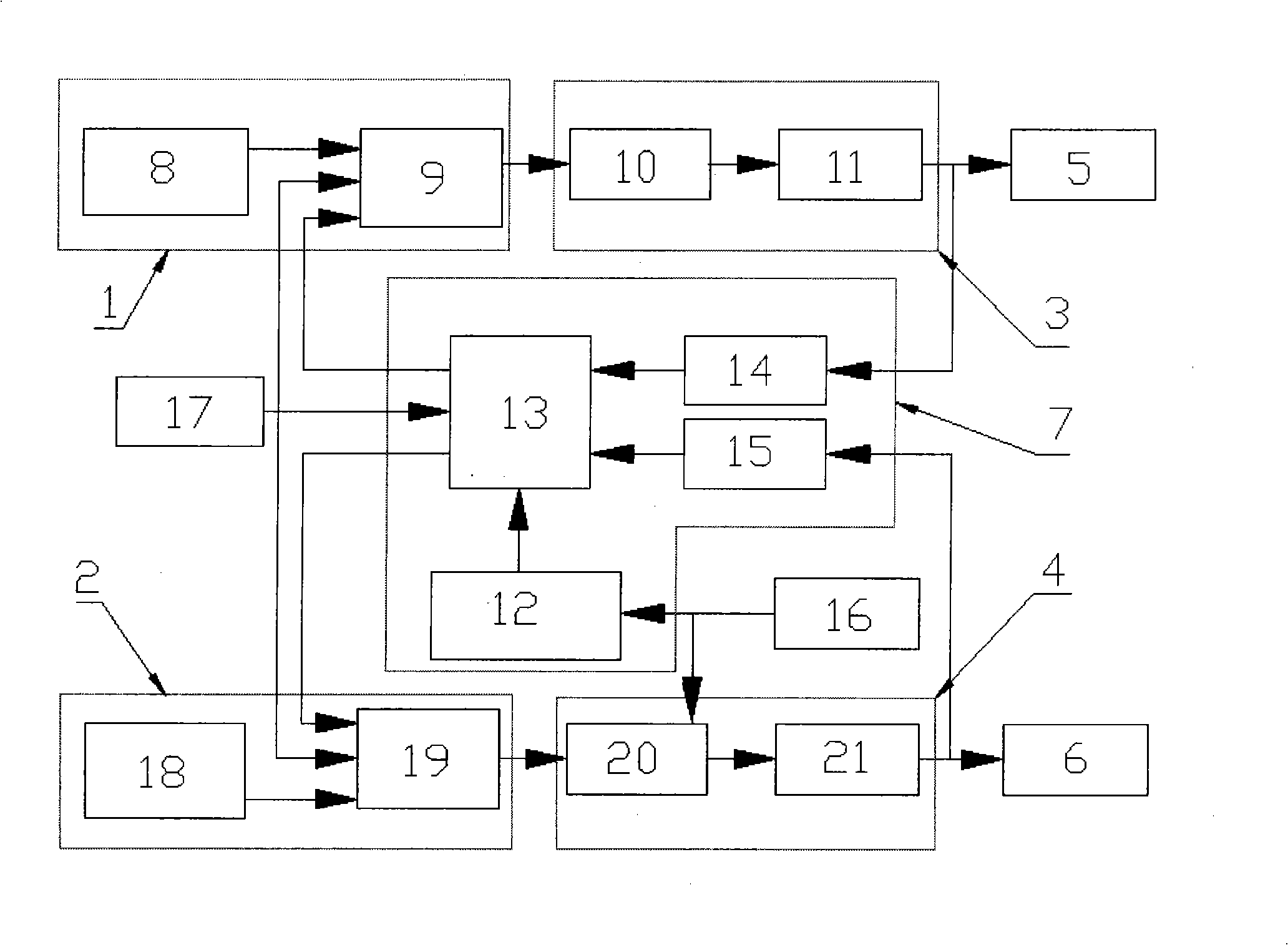
[0013] Referring to the accompanying drawings, the temperature detection and control system of the intermediate frequency hydraulic pipe bender includes programmable and control interfaces 1 and 2, the output end of the PID regulator 9 of the programmable and control interface 1 and the rectification trigger unit 10 of the intermediate frequency power controller 3 The input end of the intermediate frequency output unit 11 of the intermediate frequency power controller 3 is connected with the power input signal end of the intermediate frequency induction heating coil 5, and the output end of the PID regulator 19 of the programmable and control interface 2 is connected with the stepper motor and The input end of the stepper motor 20 of the drive control unit 4 is connected, the power output end of the stepper motor and t...


PUM


Abstract

The invention relates to a temperature detection and control system of a medium frequency hydraulic pipe bender, which comprises programmable and control interfaces (1, 2), wherein the programmable and control interface 1 is connected with a medium frequency power supply controller 3 which is connected with a medium frequency induction heating ring 5, the programmable and control interface 2 is connected with a stepping motor and a drive control unit 4 which are mechanically fixedly connected with a medium frequency induction heating ring 6; the medium frequency power supply controller 3, the stepping motor and the drive control unit 4 are all connected with a temperature detection processing unit 7, an infrared swing temperature measurement mechanism 12 in the temperature detection processing unit 7 transmits real-time signals into a temperature identifier 13, the real-time signals are compared with signals transmitted by the programmable and control interfaces (1, 2) and are processed so as to achieve the purposes of heating a steel pipe and adjusting the distance between the induction ring and the steel pipe and ensure that the temperature difference of an inner arc and an outer arc is within set temperature, thereby realizing temperature detection and automatic control of the medium frequency hydraulic pipe bender.

Description

technical field [0001] The invention relates to a detection and control system, in particular to a temperature detection and control system of an intermediate frequency hydraulic pipe bender. Background technique [0002] The heating and temperature detection and control of the steel pipe are important links to ensure the quality of the bent pipe. There are two situations in the steel pipe bending process: (1) With the increase of the bending angle, the position of the steel pipe in the horizontal plane changes at any time, and at the same time the heating area of ​​the steel pipe also drifts, and the fixed temperature measuring probe cannot measure the required temperature. The highest temperature point is measured in the area, and it also causes the temperature difference between the inner and outer arcs of the heated part of the steel pipe to change. (2) The oxide skin attached to the surface of the steel pipe and the water vapor mass on the temperature measuring optical...

Claims


Application Information

Patent Timeline
Patent Type & Authority Applications(China)
IPC IPC(8): G01J5/00G05D23/19
Inventor 曹文胜董建虎刘积录安利娟辛宏斌杨丹锋
Owner CHINA NAT HEAVY MACHINERY RES INSTCO
Why Eureka
Try Eureka