Process and apparatus for producing nanofiber and polymer web

A nanofiber and manufacturing method technology, which is applied in the field of manufacturing and device of nanofibers and polymer meshes, can solve the problems of complex device structure, inability to stack and distribute to give full play to effects, and rising equipment costs.

Inactive Publication Date: 2009-09-23
PANASONIC CORP
View PDF6 Cites 32 Cited by
  • Summary
  • Abstract
  • Description
  • Claims
  • Application Information

AI Technical Summary

Problems solved by technology

[0008] However, in Figure 21 and Figure 22A , Figure 22B In the structure shown, in order to produce a polymer network with higher productivity, the arrangement interval of the nozzles 81 on the spinning unit 82 and the arrangement intervals of the nozzles 81 in each multi-nozzle 81A are reduced to increase the unit area. When the number of nozzles, such as Figure 23 As shown, since the polymer substances flowing out from the nozzles 81 are charged with the same polarity, the polymer substances repel each other as shown by the arrow G, and the outflow of the polymer substances from the nozzle 81 in the center is hindered. At the same time, the outflow direction of the polymer substance from the nozzle 81 of the peripheral part will be towards the outside, so that the accumulation distribution of nanofibers on the collector electrode 86 will be extremely reduced in the central part and concentrated in the peripheral part, and there will be no way to make a uniform polymer substance. mesh problem
[0009] In addition, when the charge distribution plate 87 is arranged near the front end of the nozzle 81, as Figure 24 As shown, the electrical interference between the nozzles 81 can be reduced, and by forming the electric field E from the charge distribution plate 87 toward the collector electrode 86, the polymer material flowing out from each nozzle 81 can be accelerated toward the collector electrode 86. ,and Figure 23 Compared with ti

Method used


Image

  • Process and apparatus for producing nanofiber and polymer web
  • Process and apparatus for producing nanofiber and polymer web
  • Process and apparatus for producing nanofiber and polymer web

Examples


Embodiment approach 1

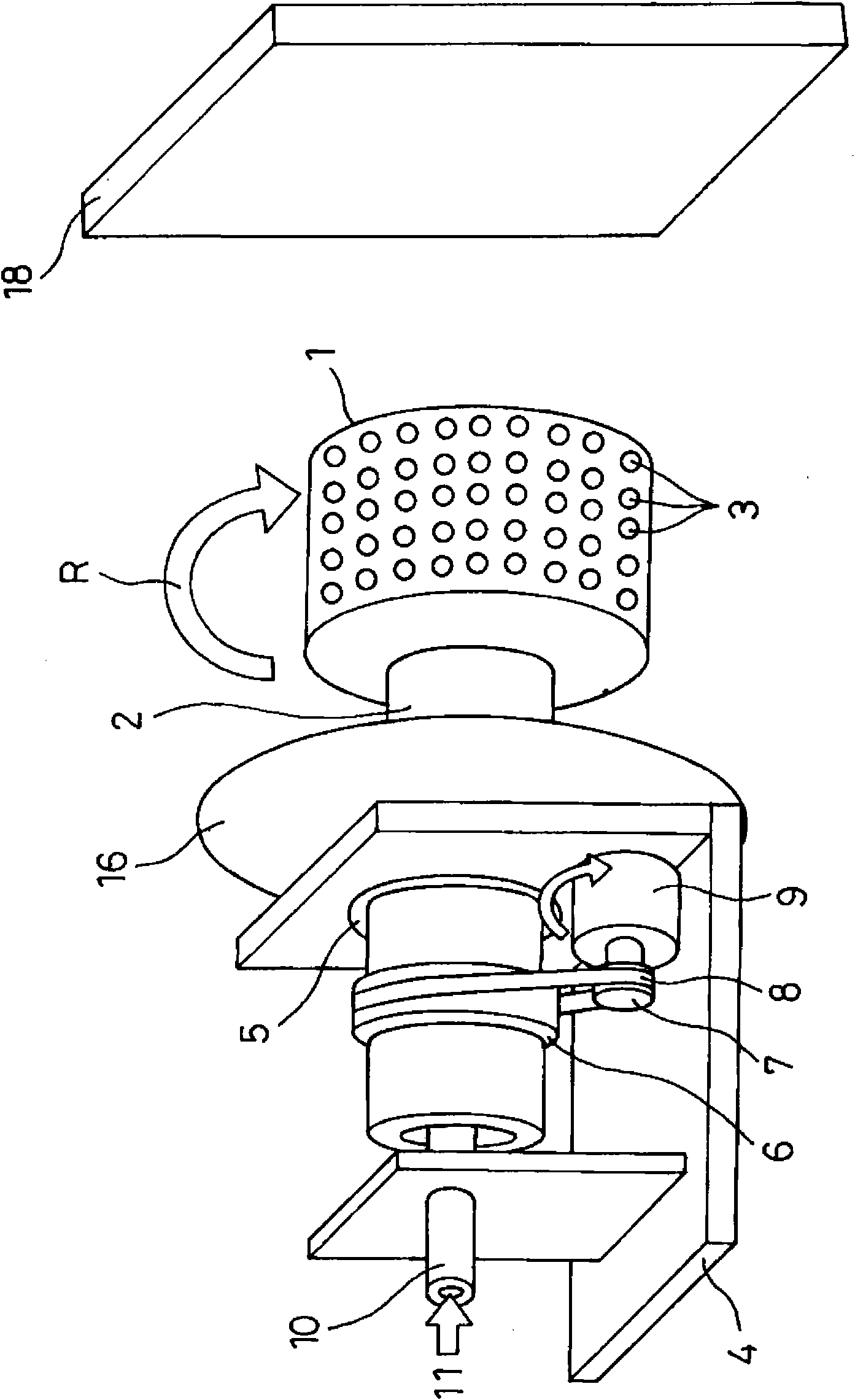
[0062] First, refer to Figure 1 ~ Figure 6C Embodiment 1 of the manufacturing apparatus of the polymer network of this invention is demonstrated.

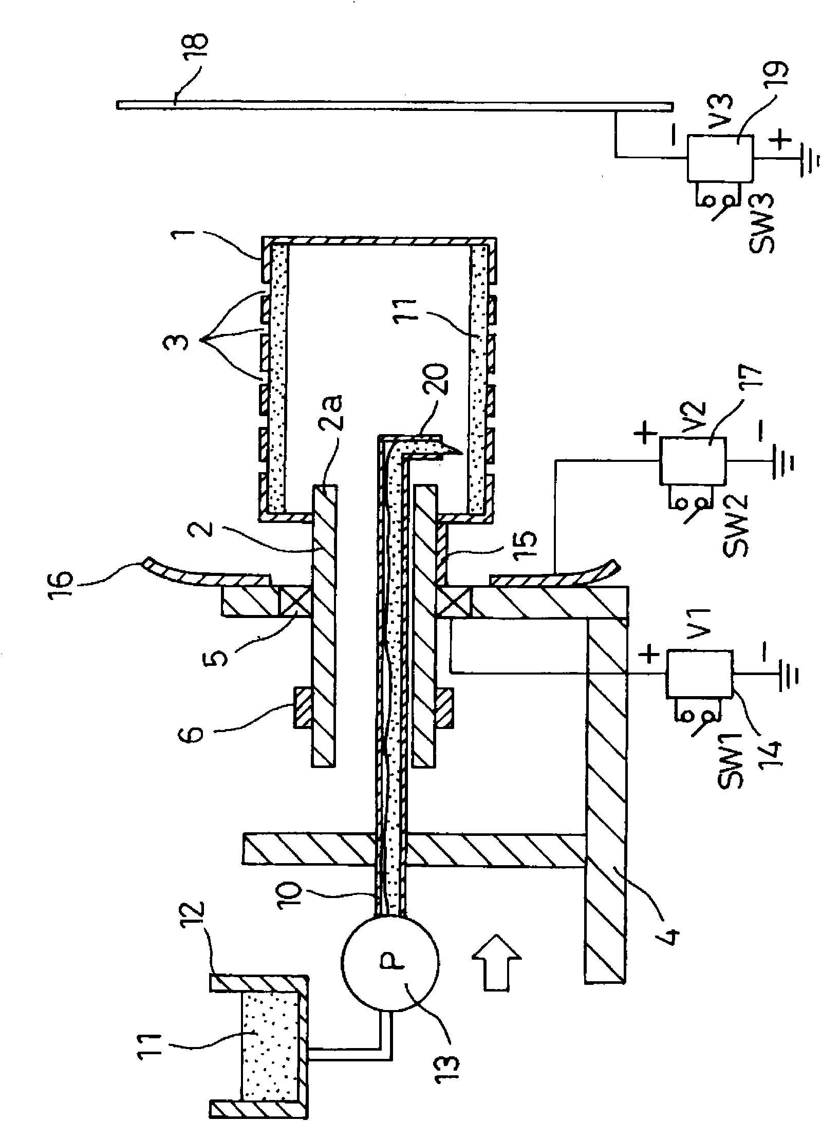
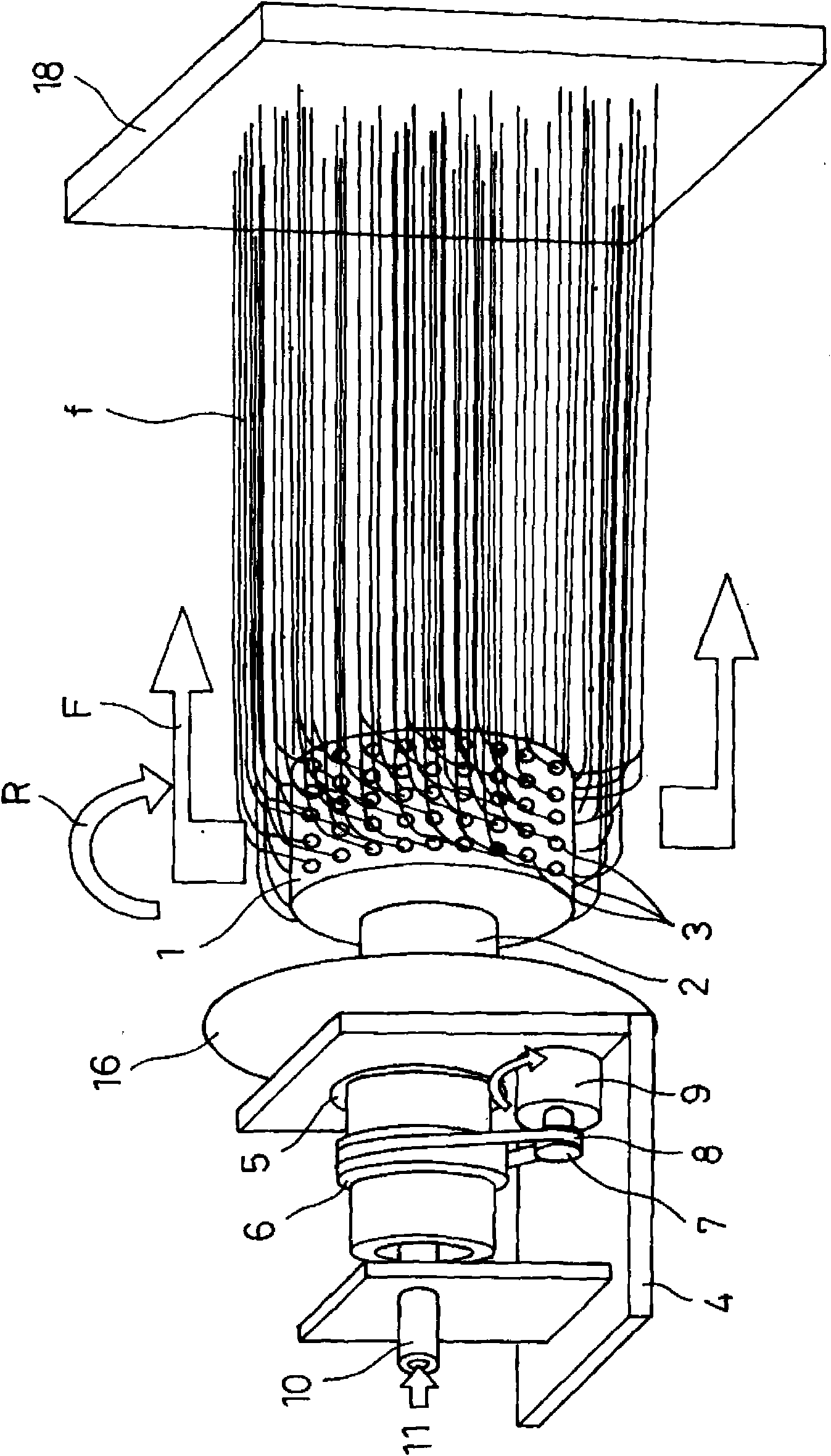
[0063] exist Figure 1 ~ Figure 3 Among them, symbol 1 is a cylindrical container with a diameter of 20 to 500 mm as a rotating container. The axial center part of one end is penetrated by the end of the rotating cylinder 2 and fixed integrally with the rotating cylinder 2 so that it can rotate around the axis. The form rotating like the arrow R is supported by the rotating cylinder 2 . The rotating cylinder 2 is made of a material with better insulation. The other end of the cylindrical container 1 is closed, and many small holes 3 with a diameter of about 0.01 to 2 mm are formed on the peripheral surface at intervals of several mm. In addition, the small hole 3 may be formed by a hole directly opened on the peripheral wall of the cylindrical container 1, or may be constituted by a short nozzle member attached to the periphera...

Embodiment approach 2

[0080] Next, refer to Figure 7 ~ Figure 10 Embodiment 2 of the manufacturing apparatus of the polymer network of this invention is demonstrated. In addition, in the description of the following embodiments, the same reference numerals are assigned to the same components as those in the above-mentioned embodiment, and description thereof will be omitted, and only main differences will be described.

[0081] In the above-mentioned embodiments, an example in which a predetermined amount of polymer solution 11 is supplied into the cylindrical container 1 according to the production amount of the polymer network has been described. The amount of the polymer solution 11 is detected, and the operation control of the supply pump 13 is performed based on the detection result so that the cylindrical container 1 contains a substantially constant amount of the polymer solution 11 .

[0082] exist Figure 7 Among them, a storage capacity detection device 25 is provided. The storage capa...

Embodiment approach 3

[0088] Next, refer to Figure 11 Embodiment 3 of the manufacturing apparatus of the polymer network of this invention is demonstrated.

[0089] In this embodiment, if Figure 11 As shown, an air blower 34 is arranged between the cylindrical container 1 and the reflective electrode 16 on one side thereof. Specifically, air blowing blades 35 are installed on the rotating cylinder 2 at a position between the reflective electrode 16 and the cylindrical container 1, and as the rotating cylinder 2 rotates, the wind blows toward the direction of the cylindrical container 1 as indicated by arrow D. Air on the other side.

[0090] According to this structure, the solvent evaporated by the air blowing of the air blowing device 34 is quickly discharged, and the concentration of the solvent in the surrounding environment will not increase. to generate the desired nanofiber f. In addition, it is also possible to more effectively deflect the flow direction of the nanofiber f in the prod...


PUM


Abstract

A process and apparatus for producing nanofiber and polymer web, the electroconductive rotary vessel (1, 36) having a plurality of small holes (3) is rotated while supplying a polymer solution (11), prepared by dissolving a polymer material in a solvent, into the rotary vessel (1, 36). Electric charges are applied by electrifying means (14, 19) to the polymer solution (11) which flows from the small holes (3) in the rotary vessel (1, 36). The flowout linear polymer solution (11) is stretched by electrostatic explosion induced by centrifugal force and the evaporation of the solvent to produce nanofibers (f) formed of a polymer material. The nanofibers (f) in the course of the production thereof are allowed to flow so as to be deflected from one side to the other side in a shaft center direction of the rotary vessel (1, 36) by a reflection electron (16) and/or air blow means (34, 46, 59) and to be deposited to produce a polymer web, whereby nanofibers and a polymer web using the nanofibers can be produced with good productivity uniformly and in a simple construction.

Description

technical field [0001] The invention relates to a method and a device for manufacturing a nanofiber formed of a polymer substance and a high-porosity polymer web (polymer web) formed by stacking the nanofiber. Background technique [0002] Conventionally, an electrospinning method (charge induction spinning method) is known as a method for producing nanofibers formed of a polymer substance and having a submicron-scale diameter. In the conventional electrospinning method, by supplying a polymer solution to a needle-shaped nozzle to which a high voltage is applied, the polymer solution flowing out in a linear form from the needle-shaped nozzle is charged, and the solvent of the polymer solution Evaporation, the distance between the charged charges becomes smaller, and the Coulomb force acting becomes larger. When the Coulomb force exceeds the surface tension of the linear polymer solution, the linear polymer solution is explosively extended. By making the The phenomenon calle...

Claims


Application Information

Patent Timeline
IPC IPC(8): D01D5/04D01D5/18D04H1/72D04H1/728
Inventor 高桥光弘竹泽幹夫冨永善章黑川崇裕石川和宜住田宽人
Owner PANASONIC CORP
Why Eureka
Try Eureka