
Horological movement with constant-torque transmission of power between the power source and the mechanical oscillator

A mechanical oscillation and energy source technology, applied to mechanically driven clocks, instruments, clocks, etc., can solve the problems of high cost and application complexity

Inactive Publication Date: 2009-09-23
SOWIND
View PDF0 Cites 2 Cited by
  • Summary
  • Abstract
  • Description
  • Claims
  • Application Information

AI Technical Summary

Problems solved by technology

[0008] [08] Although these mechanisms have been known since the 16th century, their application has remained complex and costly, especially in implementing chains involving a large number of parts.
This manufacturing complication becomes critical when it comes to applying the mechanism inside a wristwatch, and makes the clock available only to a fairly limited number of people

Method used


Image

  • Horological movement with constant-torque transmission of power between the power source and the mechanical oscillator
  • Horological movement with constant-torque transmission of power between the power source and the mechanical oscillator
  • Horological movement with constant-torque transmission of power between the power source and the mechanical oscillator

Examples


Embodiment Construction

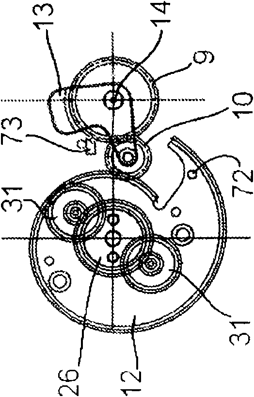
[0026] [26] In all figures, for reasons of clarity, only those parts useful for understanding the invention are shown.

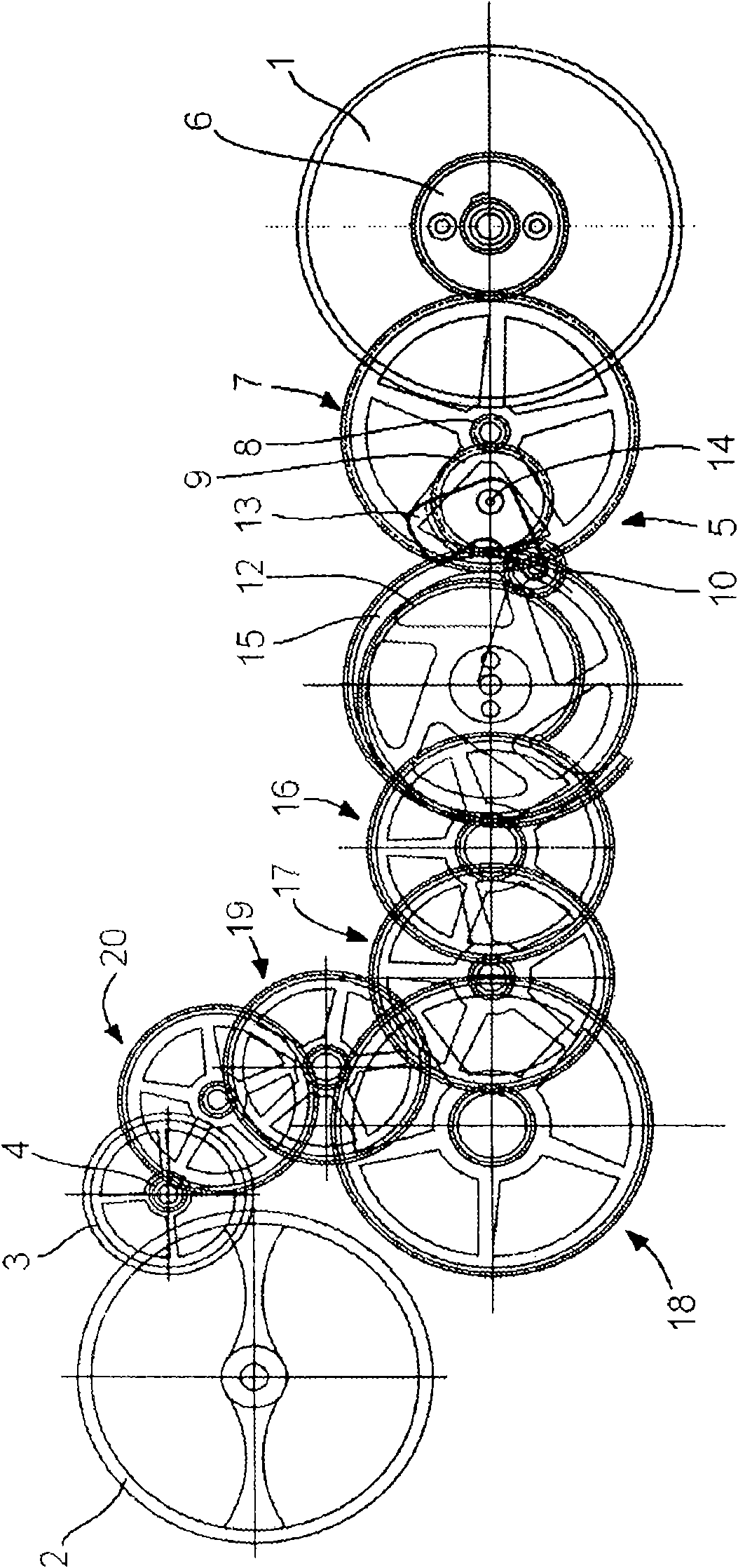
[0027] [27] Figure 1a A simplified top view of a part of a clock movement with compensating means according to a first embodiment of the invention is shown. More precisely, only those parts are shown that play a role in the kinematic chain associated with the transfer of energy from the energy source to the mechanical oscillator whose oscillation is sustained due to this energy.

[0028] [28] Schematically, said energy source takes the form of a barrel 1 housing a spring (see Figure 2a ), said spring is used to maintain the oscillation of a balance wheel 2, in particular through a running train and an escapement, the wheel 3 and pinion 4 of which are only schematically shown.

[0029] [29] The mainspring is of a conventional type, the torque output of which is transmitted to the running wheel train is known to vary with its tension, which may jeopardize t...


PUM


Abstract

The present invention relates to a movement for a timepiece comprising a power source (1, 22) mounted on a frame (24) and having a variable output torque as a function of its degree of winding. The power source is designed to maintain the oscillating movement of a mechanical oscillator (2, 3, 4) through a going train comprising a compensating device (5). The latter has an input connected kinematically to the power source, directly or via at least one wheel assembly, and an output connected kinematically to the mechanical oscillator, and is constructed so as to transmit a constant torque to the mechanical oscillator regardless of the degree of winding of the power source.; To this end, the compensating device comprises a cam (12, 84) whose periphery, which is of variable radius, extends approximately in a general plane, the variations of the radius of said cam being a function of the variations of the output torque of said power source, and said cam also having peripheral teeth. The compensating device further comprises an intermediate connecting mechanism (9, 10, 13, 83) so designed as to mesh with the teeth of said cam and provide a kinematic connection with little or no slip between said periphery of the cam and said going train.

Description

technical field [0001] [01] The invention relates to a movement for a timepiece, said movement comprising an energy source mounted on a frame and having an output torque that varies with its winding. [0002] [02] Said energy source is used to maintain the oscillating motion of the mechanical oscillator by means of a running gear train comprising a compensating device. The compensating device has an input kinematically connected to the energy source directly or via at least one wheel assembly, and an output kinematically connected to the mechanical oscillator, And the compensating means is configured to deliver a substantially constant torque to the mechanical oscillator regardless of the tightening of the energy source. Background technique [0003] [03] Movements of this type have long been known, especially in the field of horology, in order to be able to use as a source of energy a mainspring providing an important reserve of energy, while having this mainspring applied...

Claims


Application Information

Patent Timeline
IPC IPC(8): G04B1/22
CPCG04B1/22
Inventor A·帕皮
Owner SOWIND
Learn More