
Image pick-up device and display device

一种图像拾取装置、显示装置的技术,应用在图像通信、静态指示器、电视等方向,能够解决难以获得输出值等问题,达到减少大幅下降、增加速度、实现多点识别的效果

Inactive Publication Date: 2009-09-23
JAPAN DISPLAY INC
View PDF7 Cites 17 Cited by
  • Summary
  • Abstract
  • Description
  • Claims
  • Application Information

AI Technical Summary

Problems solved by technology

[0003] When realizing the image pickup device of the display function-integrated type described above using the well-known low-temperature polysilicon technology, it is considered that it is difficult to obtain an accurate output value because it is impossible to ignore the signal attenuation caused by the parasitic capacitance in the panel

Method used


Image

  • Image pick-up device and display device
  • Image pick-up device and display device
  • Image pick-up device and display device

Examples


no. 1 example

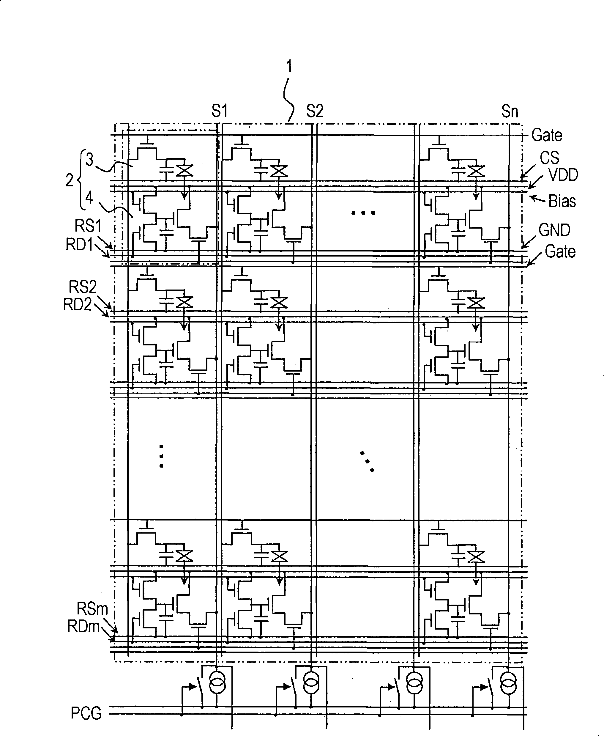
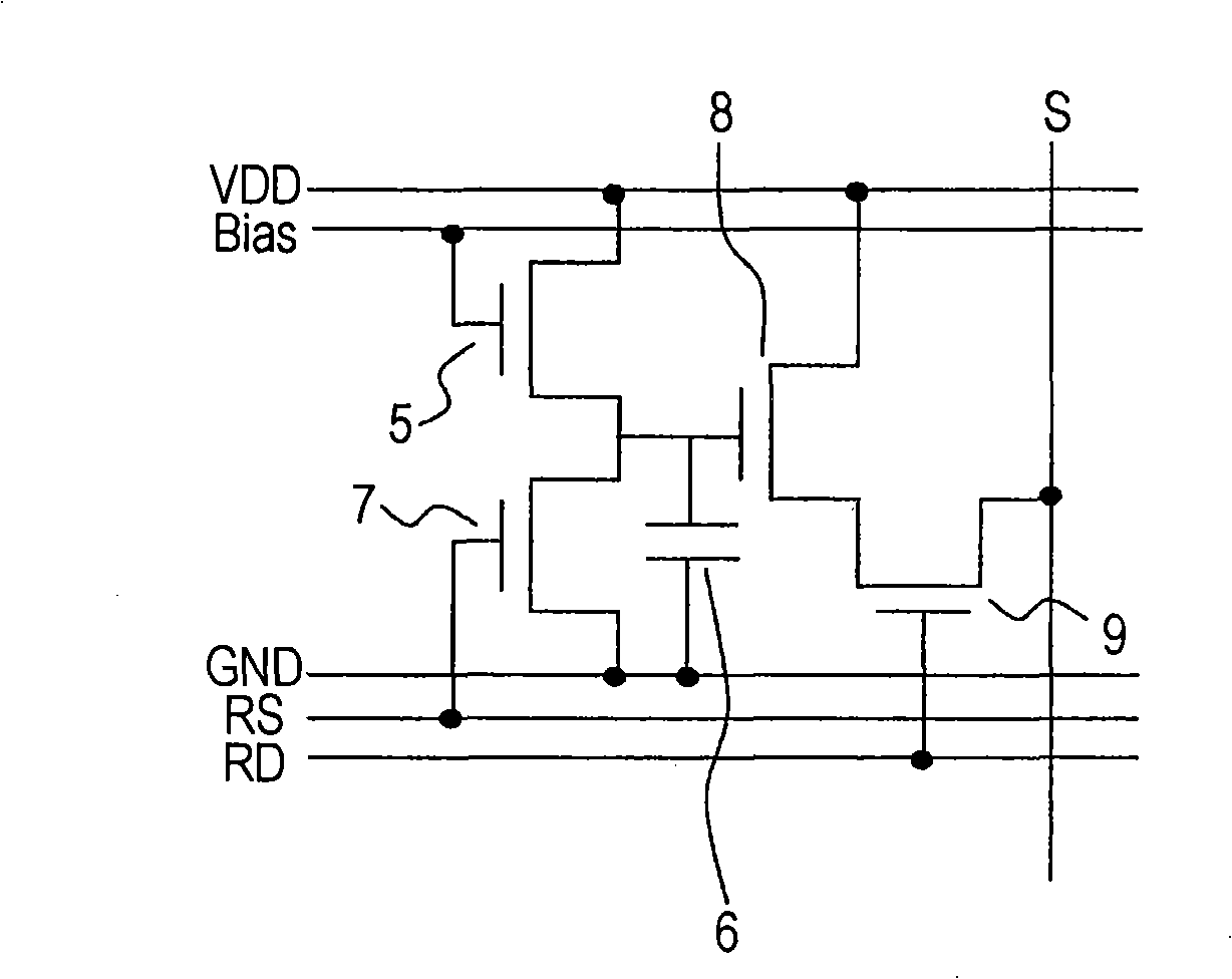
[0027] First, the first embodiment of the present invention will be described. figure 1 It is a circuit diagram showing an example of a schematic structure of a display device according to the present invention. figure 2 It is a circuit diagram showing the first embodiment of the image pickup device as the main part of the display device.

[0028] First, the entire display device is described. The display device described in the embodiment is a display device that integrates a display function and an image pickup function. In general classification, such as figure 1 As shown, the display is configured by including an image display area portion 1, a backlight or front light used as a light source (but not shown), and a drive circuit portion (but not shown) for performing drive control of the image display area portion 1. Device.

[0029] A plurality of pixel units 2 arranged in a matrix constitute an image display area section 1. In addition, each pixel unit 2 is composed of a d...


PUM


Abstract

An image pick-up device includes: a photoelectric converter (5) which converts light into electric charge; an accumulation capacitor (6) which accumulates charge converted by the photoelectric conversion element(s); reset means (7) for discharging electric charge from the accumulation capacitor (6); and an amplification thin film transistor (8) which receives and amplifies electric charge accumulated in the accumulation capacitor (6) and outputs the amplified charge. The amplification thin film transistor (8) forms a source follower circuit.

Description

Technical field [0001] The present invention relates to an image pickup device and a display device including a photoelectric conversion element. Background technique [0002] Although photoelectric conversion elements such as CCD (Charge Coupled Device) sensors and CMOS (Complementary Metal Oxide Semiconductor) sensors are generally considered to be image pickup devices that pick up images, thin film transistors (hereinafter referred to as “thin film transistors”) have been proposed in recent years. (Referred to as "TFT") combined with a capacitor or the like to function as a photoelectric conversion element. As an example of such an image pickup device, for example, there is an image pickup device that includes a liquid crystal display element, a TFT serving as a photoelectric conversion element for each pixel arranged in a matrix, and the like, and also includes a backlight or front light used as a light source. . The image pickup device is configured so that information input...

Claims


Application Information

Patent Timeline
Patent Type & Authority Applications(China)
IPC IPC(8): H04N5/335G02F1/133G09G3/20G09G3/36H04N1/028G06F3/041G06F3/042H04N25/00
CPCG09G2300/0465G09G3/3648G02F2001/13312G02F1/13338G06F3/0412G06F3/042G02F1/13312
Inventor 松井雅史仲岛义晴寺西康幸
Owner JAPAN DISPLAY INC
Learn More