Vibration isolation device and application thereof

A vibration isolation and coupling device technology, which is applied in protection devices, non-rotational vibration suppression, roads, etc., can solve the problems of very difficult on-site maintenance restrictions, large size of coupling sleeve, cost reduction and transportation, etc., and achieve vibration isolation effect Good, the effect of improving strength and reducing production cost

Active Publication Date: 2009-09-30
尹学军 +1
View PDF0 Cites 12 Cited by
  • Summary
  • Abstract
  • Description
  • Claims
  • Application Information

AI Technical Summary

Problems solved by technology

The Chinese patent No. ZL2004100354411 discloses a built-in vibration isolation device. The coupling sleeve of the vibration isolation device is arranged in the floating plate, and the supporting block fixedly arranged on the coupling sleeve is supported as a direct force-bearing element during operation. On the spring vibration isolator, after long-term use, the relevant parts are prone to fatigue damage, open welding, and corrosion. However, since the connecting sleeve has been integrated with the floating plate, it cannot be directly replaced and repaired on site It is very difficult to be limited by the location and the internal space of the connecting sleeve
At the same time, in order to repair and replace the spring isolator at any time, the traditional built-in vibration isolator adopts the technical scheme that the spring isolator can be directly taken out through the through hole on the connecting sleeve, which requires that the size of the through hole must be slightly larger than the spring The size of the vibration isolator, so the size of the connecting sleeve is correspondingly larger, which not only takes up more space but also is not conducive to reducing costs and transportation

Method used


Image

  • Vibration isolation device and application thereof
  • Vibration isolation device and application thereof
  • Vibration isolation device and application thereof

Examples


Embodiment 1

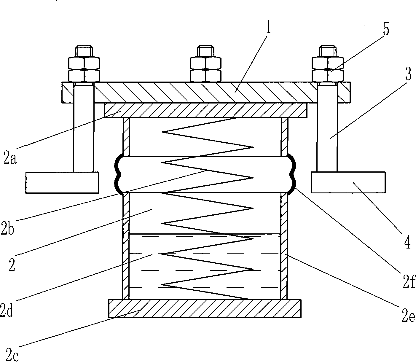
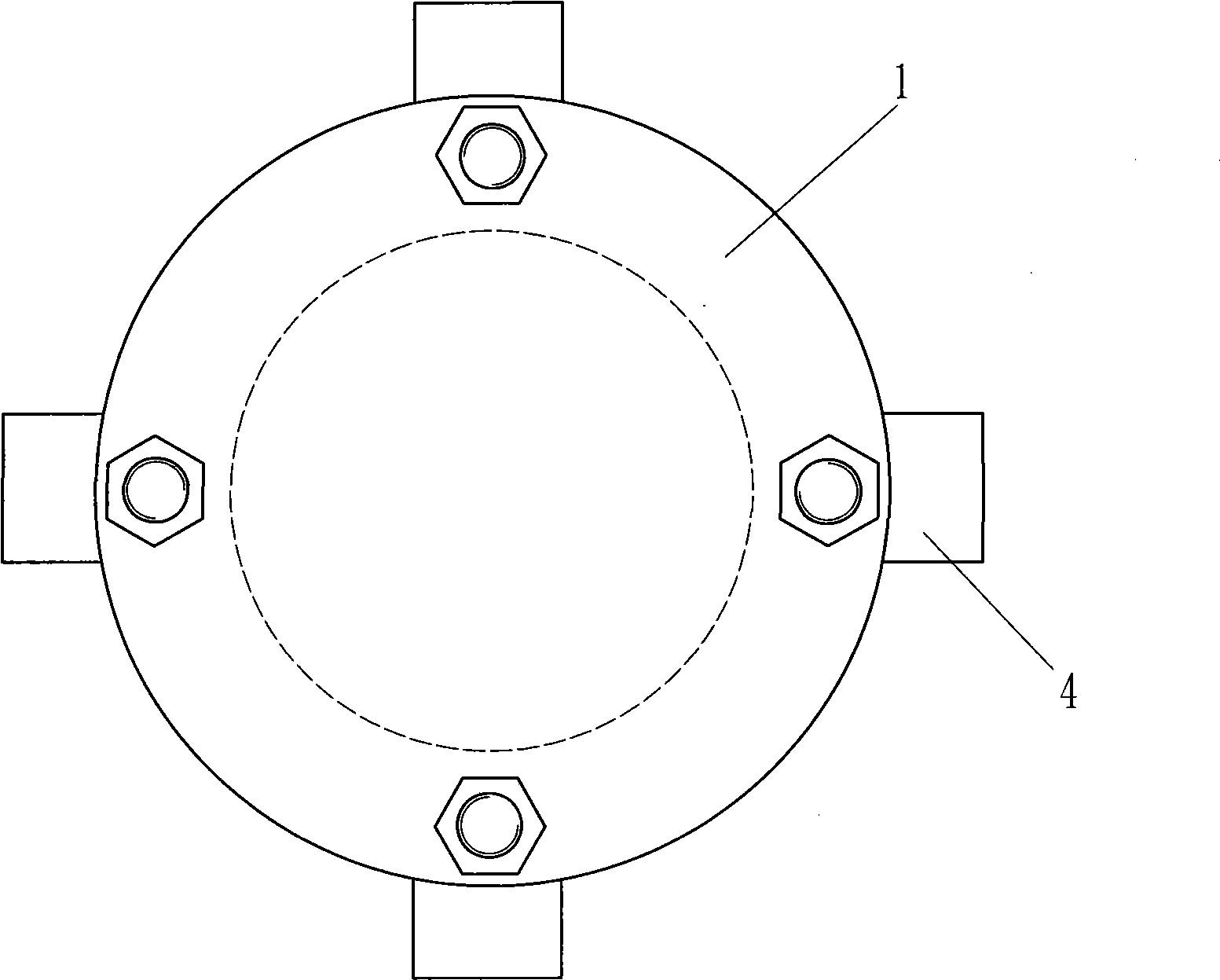
[0030] Such as figure 1 , figure 2 The vibration isolation device of the present invention shown includes a supporting block 1 and a spring vibration isolator 2. The spring vibration isolator 2 is located below the supporting block 1. The spring vibration isolator 2 consists of an upper top plate 2a, a spring 2b, and a lower top plate 2c. , Liquid damper 2d, damper cylinder 2e and dust cover 2f. The support block 1 is provided with four rotatable booms 3, and the lower part of the boom 3 is horizontally provided with a hook block 4 extending outward. The rotatable boom 3 is arranged through the supporting block 1, and the upper part is provided with a thread structure and is fitted with a lock nut 5.

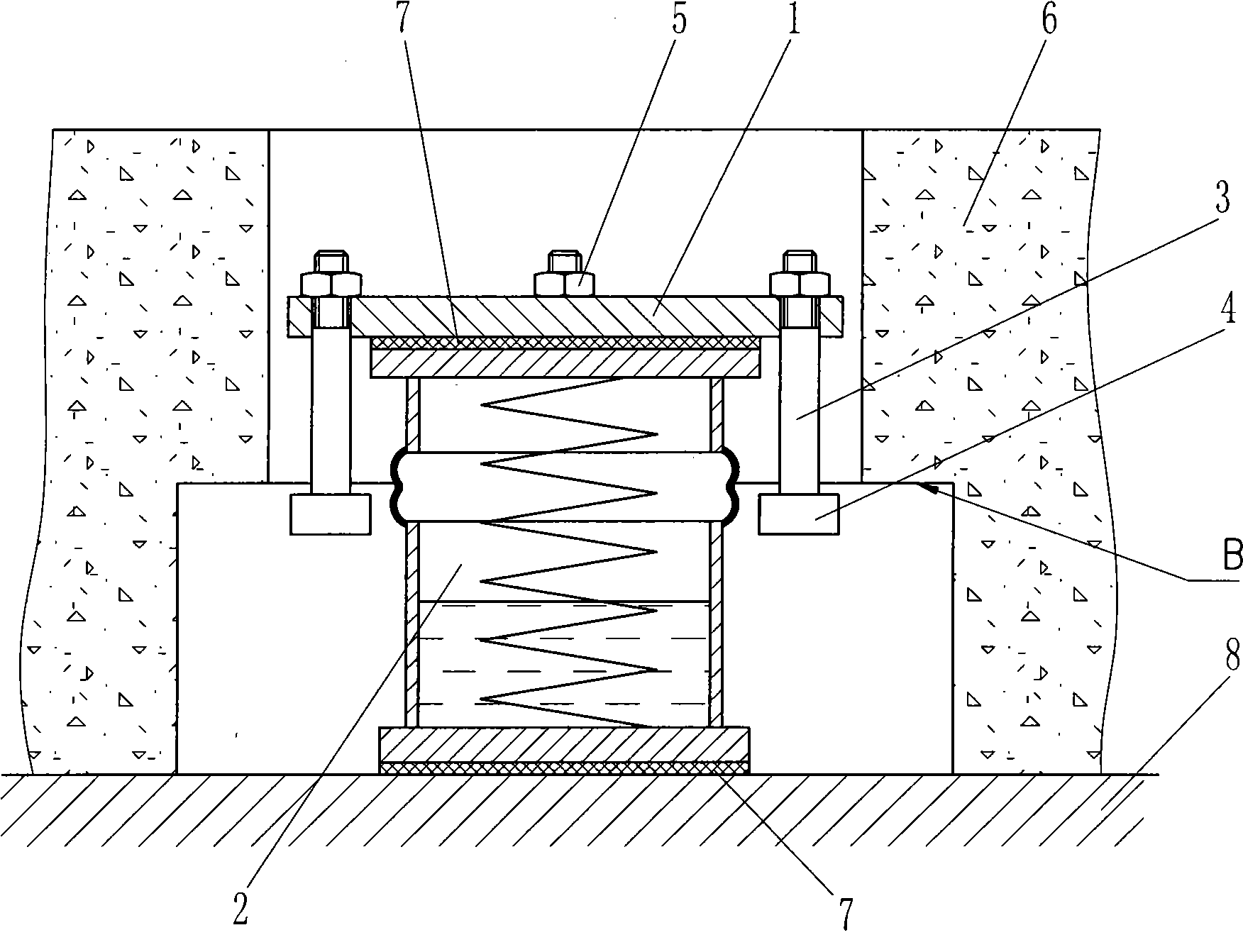
[0031] Such as image 3 As shown, the vibration isolation member 6 is a floating plate of a floating track bed. In application, the supporting block 1 and the spring vibration isolator 2 are sequentially placed in the reserved through holes of the floating plate 6, and the reserve...

Embodiment 2

[0037] In order to facilitate the lifting of the component to be vibration-isolated directly from above and the spring vibration isolator can be directly installed from above, such as Figure 5 , Figure 6 The difference between the vibration isolation device of the present invention shown in the first embodiment is that a gasket 10 is added. The gasket 10 is placed between the spring isolator 2 and the supporting block 1, which can pass through the center hole of the supporting block and be connected to the supporting block. A staggered overlap is formed between the stoppers, and a center hole is provided on the support stopper 1 corresponding to the size of the washer 10 and the spring vibration isolator 2. In order to facilitate the lifting operation, a lifting block 11 is provided between the lock nuts 5.

[0038] When used in the track floating plate, such as Figure 7 As shown, a reserved through hole corresponding to the shape of the vibration isolation device is preset on ...

Embodiment 3

[0044] Such as Picture 9 As shown, the difference from the second embodiment is that a shoulder 31 is provided on the boom 3, and the shoulder 31 is used to cooperate with the supporting block 1 to limit the position, and the boom 3 is connected to the hook block by a threaded structure provided at its lower end. And use the lock nut to lock the hook block. When the boom is assembled with the supporting block, the boom can be passed through the supporting block from top to bottom and then connected with the hook block. In addition, the setting of the jacking block 11 can also be integrated with the lock nut 5. In this way, if the size of the threaded section of the upper part of the boom 3 is standardized, the jacking block integrated with the lock nut can be removed and used for the next vibration isolator after completing the jacking of one vibration isolator. The jacking up is conducive to saving materials and further reducing costs. The gasket 10 is provided in multiple piece...


PUM


Abstract

The invention relates to a vibration isolation device for reducing the vibration of building units and equipment foundations in the running process of railbound vehicles, which comprises a bearing stop dog and a spring vibration isolator. The bearing stop dog and the spring vibration isolator are arranged in reserve through holes of vibration isolating members; the spring vibration isolator is arranged below the bearing stop dog; the bearing stop dog is provided with at least two hanger rods capable of rotating, translating or swinging; and a transverse extending-outward hanging-connecting stop dog is arranged at the lower part of the hanger rod. The vibration isolation device has compact and reasonable structure and convenient maintenance, solves the problem in the prior art that the bearing stop dog is difficult to restore once being damaged, has good vibration isolation effect, saves materials and reduces the cost on the premise of not influencing the vibration reducing effect, has wider range of application, is easy to process and manufacture and considers economic effect and environmental protection effect; a jacking mounting method of the vibration isolation device has convenient operation and reliable effect; and the vibration isolation device provides more application choices for vibration noise environment control of the construction of equipment, the railbound vehicles and building factories, is particularly suitable for the vibration isolation of a rail floating road bed and building floor or equipment foundation, and has broad popularization and application prospect.

Description

Technical field [0001] The invention belongs to the field of vibration and noise control, and in particular relates to a vibration isolation device for reducing the adverse effects of vibration and noise emitted during the operation of rail vehicles or reducing the vibration of building components and equipment foundations. Background technique [0002] Vibration and noise are recognized as the most widespread public hazards. They not only affect and destroy transportation, buildings and equipment, but also directly cause harm to the human body. Therefore, vibration reduction and noise reduction have become a topic of great concern in the field of environmental protection in recent years. Among the existing vibration and noise reduction technologies, the most successful application and practice in the fields of rail transit and equipment vibration isolation is the component floating technology. The typical track bed floating technology and equipment basic floating technology, etc...

Claims


Application Information

Patent Timeline
Patent Type & Authority Applications(China)
IPC IPC(8): F16F15/06E01B9/68
CPCE02D31/08E04F15/225
Inventor 尹学军孔祥斐
Owner 尹学军
Why Eureka
Try Eureka