Electro-optic compound port machine pony roll high-voltage cable and production method thereof

A composite port machine and high-voltage technology, which is applied in the direction of insulated cables, communication cables, cable/conductor manufacturing, etc., can solve the problems of broken core damage, cable electrical induction, stress concentration, etc., to reduce space occupation, improve service life, and structure stable effect

Inactive Publication Date: 2009-09-30
SHANGHAI NANYANG ELECTRICAL APPLIANCE
View PDF0 Cites 6 Cited by
  • Summary
  • Abstract
  • Description
  • Claims
  • Application Information

AI Technical Summary

Problems solved by technology

[0002] In terms of high-voltage power and signal transmission, there are two major technical problems in the cables used in the existing port container cranes and large cranes in steel mills or power plants: first, the cables will produce electrical induction during high-voltage power and signal transmission; Second, the existing cables often need to be

Method used


Image

  • Electro-optic compound port machine pony roll high-voltage cable and production method thereof

Examples


Embodiment 1

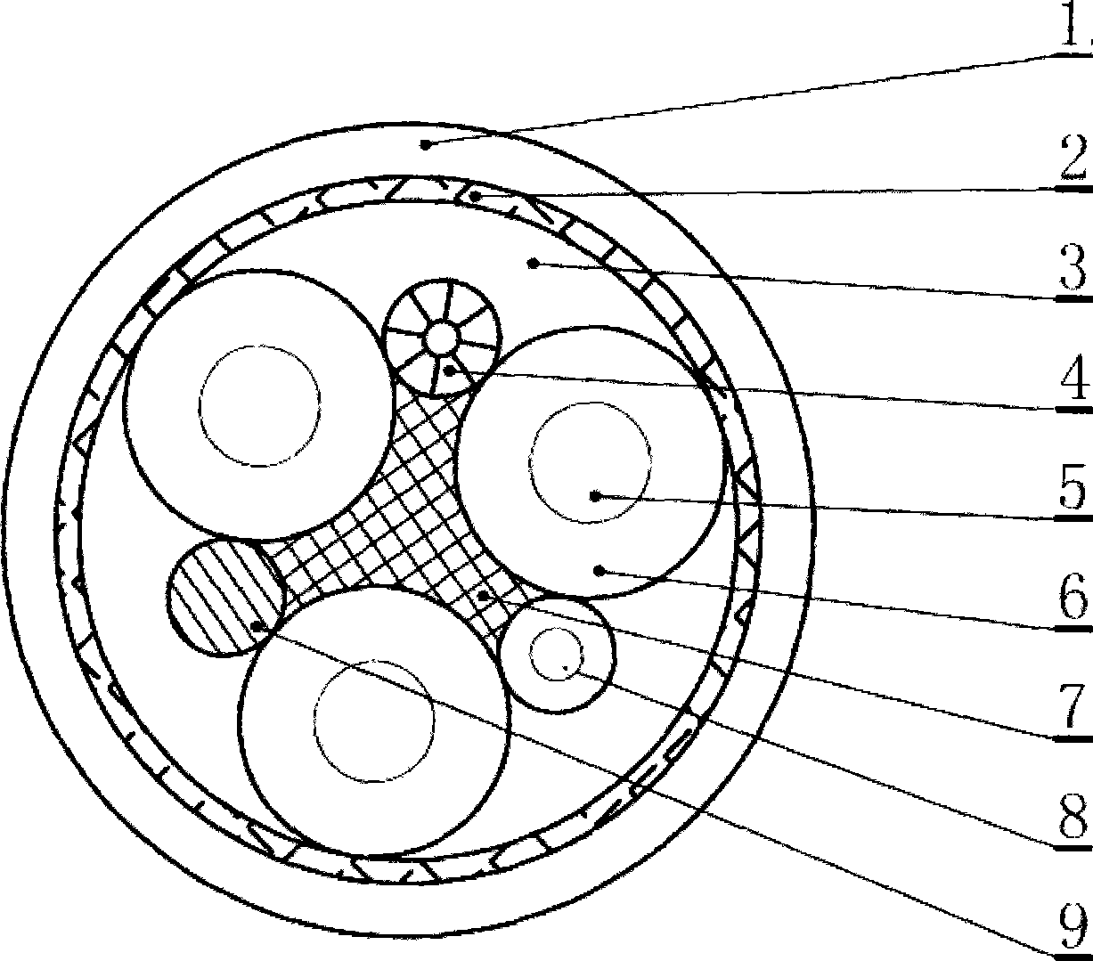
[0022] A photoelectric composite port machine coiled high-voltage cable, including three high-voltage main wire cores, an optical cable 4, a saddle frame strip 7, a reinforcement layer 2 and an outer sheath 1, a grounding core 8, a filling core 9, The high-voltage main line core, optical cable 4, grounding core 8 and filling core 9 are all placed on the saddle-shaped skeleton bar, and the optical cable 4, grounding core 8 and filling core 9 are respectively located on two adjacent ones of the three high-voltage main line cores. Between the high-voltage main wire cores, the reinforcement layer 2 is coated on the outside of the high-voltage main wire core, the optical cable 4, the grounding core 8 and the filling core 9, and the gap in the reinforcement layer 2 is filled with an inner lining layer 3, and the reinforcement layer 2 An outer sheath 1 is arranged on the outside. Wherein the high-voltage main line core includes a conductor 5 and a high-voltage insulation layer 6 extr...

Embodiment 2

[0024] A method for producing a photoelectric composite port machine coiled high-voltage cable, the steps of which are:

[0025] (1) The high-voltage main wire core is made of a tinned copper conductor and an ethylene-propylene insulating mixture;

[0026] (2) processing and making the saddle-shaped skeleton bar 7;

[0027] (3) adopt tinned copper conductor and insulating material to make high-voltage grounding core 8;

[0028] (4) adopt long-wave optical fiber unit and protective layer to make 6LWL single optical cable 4;

[0029] (5) making single core filling core 9;

[0030] (6) Twisting the structural components made in the 1-5 steps into cables according to the cable structure design requirements;

[0031] (7) Extrude the inner sheath of the neoprene mixture to ensure that the structure of the extruded sheath is tight and firm without leaving gaps, the wall thickness is uniform, the core is not biased, and the internal stress of the material is uniform and not easy to...


PUM

PropertyMeasurementUnit
Diameteraaaaaaaaaa
Diameteraaaaaaaaaa

Abstract

The invention relates to an electro-optic compound port machine pony roll high-voltage cable, which consists of three main high-voltage wire cores, an optical cable, an earthing core, a wadding core, a saddle-shaped skeleton strip, reinforcing layers and an outer sheath. The main high-voltage wire cores, the optical cable, the earthing core and the wadding core are positioned on the saddle-shaped skeleton strip; the optical cable, the earthing core and the wadding core are respectively positioned between two adjacent main high-voltage wire cores of three main high-voltage wire cores; and the reinforcing layer are covered outside the main high-voltage wire cores, the optical cable, the earthing core and the wadding core. A liner layer is filled in the interstice in the reinforcement layer, the outer sheath is arranged outside the reinforcing layer; in addition, the invention also relates to a method for producing the cable. The cable of the invention has the characteristics of no electric induction, less space occupation and long service life.

Description

technical field [0001] The invention relates to a cable used for a large mechanical device, in particular to a photoelectric composite port machinery coiled high-voltage cable, and in addition, the invention also relates to a production method of the cable. Background technique [0002] In terms of high-voltage power and signal transmission, there are two major technical problems in the cables used in the existing port container cranes and large cranes in steel mills or power plants: first, the cables will produce electrical induction during high-voltage power and signal transmission; Second, the existing cables often need to be stored in coiled (mobile) type under 10KV high voltage, and in the continuous working state of reciprocating coiling, the internal structure of the cable is easily affected by external factors such as continuous coiling and bending. Impact, resulting in component displacement, twisting, stress concentration, etc., causing mechanical damage to broken ...

Claims


Application Information

Patent Timeline
IPC IPC(8): H01B11/22H01B7/17H01B3/28H01B13/00
Inventor 孙正华陈安元陈文刚刘长洲张国平徐牮国楼志清
Owner SHANGHAI NANYANG ELECTRICAL APPLIANCE
Why Eureka
Try Eureka