Heat generation body cooling structure and drive device

A driving device and heating element technology, applied in cooling/ventilation devices, cooling/ventilation/heating transformation, electromechanical devices, etc., can solve the problems of large-scale coolant pump energy loss, large pressure loss, insufficient heat dissipation, etc. Achieve good cooling capacity, good heat dissipation capacity, and lengthen the effect

Active Publication Date: 2009-09-30
AISIN AW CO LTD +1
View PDF4 Cites 21 Cited by
  • Summary
  • Abstract
  • Description
  • Claims
  • Application Information

AI Technical Summary

Problems solved by technology

[0016] In particular, even in the case where the coolant flows through the serpentine inter-fin passages as in the heating element cooling structure described in Patent Document 4 above, since the both side wall surfaces of the heat radiation fins are formed in the same shape, the fins have the same shape. The passage width in the parallel arrangement direction of the cooling fins in the inter-fin passage is uniform, so that sufficient turbulence cannot be generated in the co...

Method used


Image

  • Heat generation body cooling structure and drive device
  • Heat generation body cooling structure and drive device
  • Heat generation body cooling structure and drive device

Examples


Embodiment Construction

[0060] Embodiments of the heating element cooling structure and the driving device including the structure according to the present invention will be described based on the drawings.

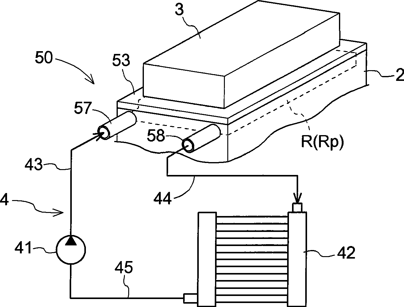
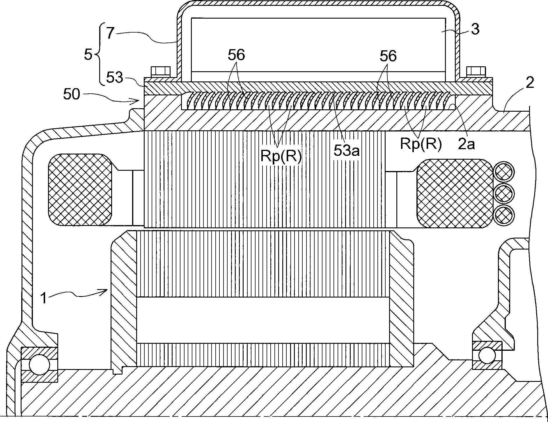
[0061] Such as figure 2 As shown, the driving device (hereinafter referred to as "this driving device") to which the present invention is applied includes: a motor 1, a driving device housing 2 for accommodating the motor 1, an inverter 3 for controlling the motor 1, and adopts the The heating element cooling structure 50 (hereinafter, referred to as "this cooling structure") of the present invention.

[0062] In addition, this driving device constitutes a driving device used in an electric vehicle, a hybrid vehicle, or the like. Therefore, the drive device housing 2 accommodates an electric motor or a generator or both of them as the electric motor 1 , a differential device, an auxiliary mechanism such as a counter gear mechanism, and the like.

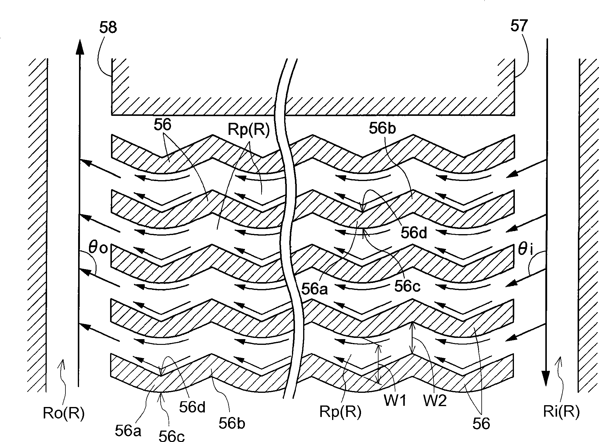
[0063] On the other hand, this cooling struct...


PUM


Abstract

A heat generation body cooling structure (50) and a drive device having the heat generation body cooling structure. The heat generation body cooling structure (50) has formed in it a refrigerant space (R) and inter-fin passages (Rp). The refrigerant space (R) is formed between a heat radiation surface (53a) thermally connected to a heat generation body and an opposite surface placed so as to face the heat radiation surface (53a). The inter-fin passages (Rp) are formed by parallelly arranging heat radiation fins (56), rising from the heat radiation surface (53a) toward the opposite surface, and allow refrigerant to flow between each adjacent pair of heat radiation fins (56). A heat radiation fin (56) is shaped in a serpentine pattern having bends in the direction of flow of the refrigerant, and both side wall surfaces (56c, 56d) of the fin (56) are shaped to be different from each other.

Description

technical field [0001] The present invention relates to a heating element cooling structure and a driving device, wherein the heating element cooling structure is such that a coolant space is formed between a heat dissipation surface thermally connected to the heating element and an opposing surface arranged opposite to the heat dissipation surface, In the coolant space, a plurality of heat dissipation fins standing upright from the heat dissipation surface toward the opposing surface are arranged in parallel, inter-fin passages through which the coolant flows are formed between the plurality of heat dissipation fins adjacent to each other, and the drive device includes : Motor, housing of the drive device for housing the above motor, [0002] An inverter that controls the motor is provided with a cooling structure for the heating element, and the inverter is used as the heating element. Background technique [0003] When a motor is used as a drive source of a vehicle, the ...

Claims


Application Information

Patent Timeline
IPC IPC(8): H05K7/20H02K9/19H01L23/36H02K11/00H01L23/473
CPCH02K11/0073H01L23/473H02K9/19H05K7/20927H02K5/20H01L21/4878H01L2924/0002H02K11/33B21J5/068H02K5/203H01L2924/00
Inventor 青木一雄鹤冈纯司安井诚二蒲田靖宫原英行熊谷政晴
Owner AISIN AW CO LTD
Why Eureka
Try Eureka