
Stirring transport tank

A technology for stirring, transporting and transporting tanks, applied in the field of transport tanks, can solve the problems affecting the quality of the contents, troublesome maintenance, and difficulty in discharging the contents, and achieve the effects of reducing sediment, good stirring performance and saving working time.

Inactive Publication Date: 2009-10-14
冯志军
View PDF0 Cites 8 Cited by
  • Summary
  • Abstract
  • Description
  • Claims
  • Application Information

AI Technical Summary

Problems solved by technology

[0003] In the prior art, the transport vehicle for transporting molten material (higher viscosity) generally has a larger capacity. Generally, an insulating layer is added outside the tank, and an insulating and heat-conducting oil pipe is provided inside to prevent the condensation or precipitation of the contents by maintaining the temperature. To the destination, and then discharge, but the transport vehicle of this structure, because the contents of the tank are in a molten state during the transportation process, a certain amount of precipitation will still be formed during the transportation process, especially for some substances with high viscosity, the precipitation phenomenon More serious, it will cause certain difficulties to the outflow of the contents, and the container needs to be cleaned regularly, the operation is complicated, the manpower consumption is large, the cost is high, the maintenance is troublesome, and it also directly affects the quality of the contents
[0004] In the prior art, there is no internal stirring of the contents of the tank during transportation, and the entire container is in a static state with a large capacity to prevent the contents from settling. The liquid materials in the tank can be fully stirred before being discharged. , to ensure the quality of the transport tanker

Method used


Image

  • Stirring transport tank

Examples


Embodiment Construction

[0038] Below in conjunction with accompanying drawing and specific embodiment the present invention is described in further detail:

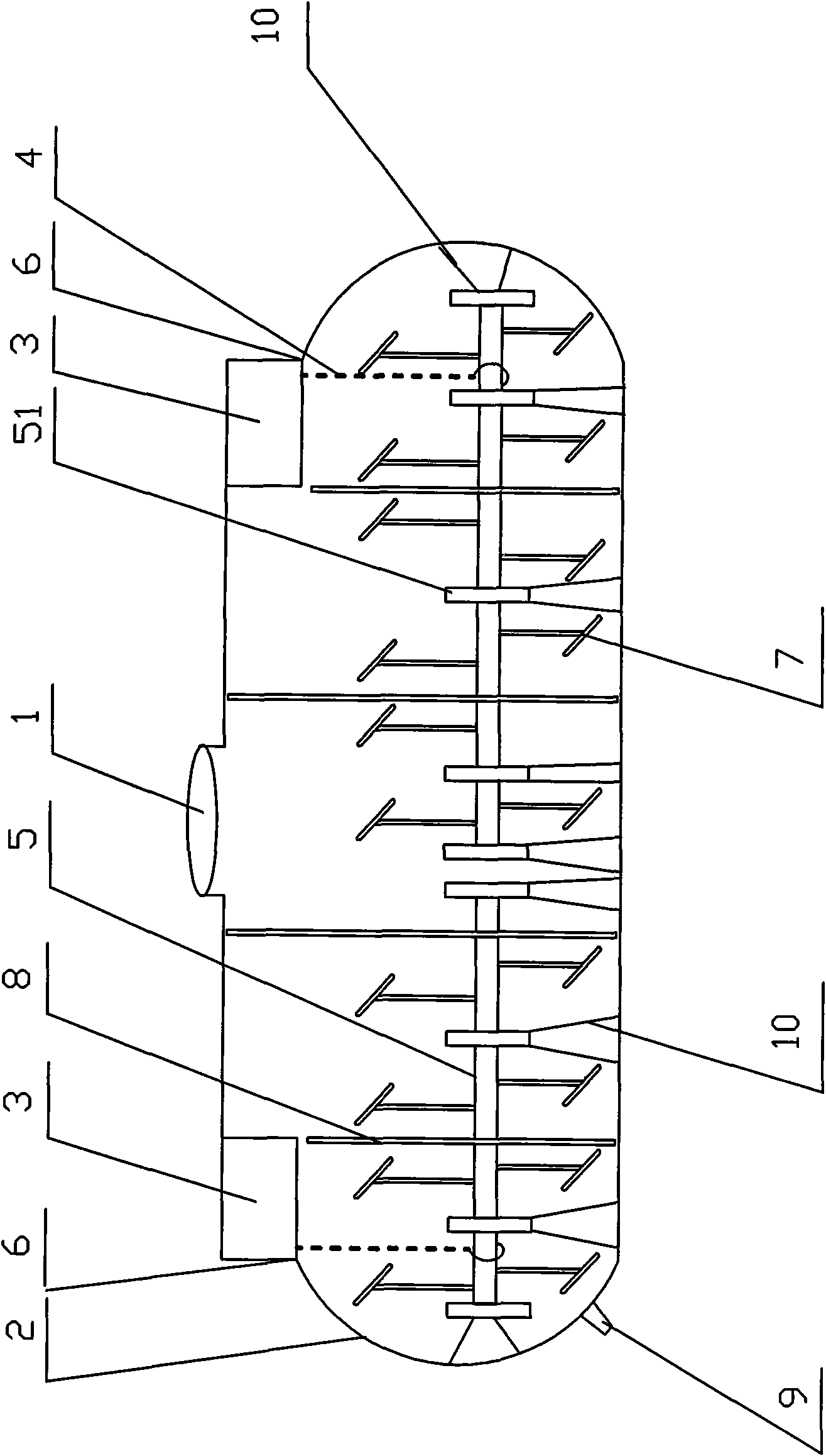
[0039] see figure 1

[0040] figure 1 It is a structural schematic diagram of the present invention. exist figure 1 Among them, the transport tank of the transport vehicle is provided with a stirring device, the stirring device includes a stirring system and a transmission system connected thereto, and the stirring system includes a stirring shaft 5 with a stirring impeller 7 engaged with a bearing sleeve 51, Agitator shaft 5 passes through dividing plate 8 (dividing plate 8 can adopt prior art, can be arched), and described agitating shaft 5 is connected with the transmission system that vehicle adds, and described transmission system comprises gear transmission case 3 and is connected with it Transmission chain 4, described transmission system is connected with the power system of vehicle, also can set up a back-up power supply (backup pow...


PUM


Abstract

The invention relates to a stirring transport tank which comprises a tank body, wherein the tank body is provided with a baffle plate and a stirrer, the stirrer comprises a driving system and a stirring system connected with the driving system, a sealing device is arranged between a chain gear transmission box of the driving system and the transport tank, the stirring system comprises a stirring shaft which is engaged with a bearing sleeve and is provided with stirring impellers, the stirring impellers are in a single shaft mode, the bearing sleeve is arranged on support frames arranged in the transport tank, the support frames are arranged corresponding to the bearing sleeve, are arranged on the side wall and the bottom of the transport tank and are fixedly connected with the internal wall of the transport tank, a driving chain of the driving system is connected with both ends of the stirring shaft of the stirring system, the stirring shaft is divided into at least two parts, the two parts of the stirring shaft have asynchronous rotating speed, and the driving system is connected with a power system of a cart body and a backup power supply. The invention has a reasonable structure, overcomes the defects of the prior art because the stirrer is arranged in the tank, can reduce sediments by about 90 percent, and relieves the labor intensity of a worker cleaning the tank.

Description

technical field [0001] The invention relates to a transport tank, in particular to a stirring transport tank. Background technique [0002] "Science and technology is the primary productive force" is the power source for countless countries to improve their national economy. "Independent innovation" is the central point for each enterprise to enhance its competitiveness and exert its subjective initiative. In the construction and transportation industry, new products with better quality, lower cost, more ingenious ideas and more practicality emerge in an endless stream. [0003] In the prior art, the transport vehicle for transporting molten material (higher viscosity) generally has a larger capacity. Generally, an insulating layer is added outside the tank, and an insulating and heat-conducting oil pipe is provided inside to prevent the condensation or precipitation of the contents by maintaining the temperature. To the destination, and then discharge, but the transport v...

Claims


Application Information

Patent Timeline
Patent Type & Authority Applications(China)
IPC IPC(8): B28C5/42B28C5/14
Inventor 冯志军
Owner 冯志军
Learn More