Method for measuring defect thickness in carbon/silicon carbide composite material

A composite material, internal defect technology, applied in the measurement device, the use of wave/particle radiation, the preparation of test samples, etc., can solve the problem that the shape of the defect cannot be captured at one time, and the efficiency is low, so as to facilitate digital analysis and improve detection efficiency. Effect

Inactive Publication Date: 2009-10-14
NORTHWESTERN POLYTECHNICAL UNIV
View PDF0 Cites 18 Cited by
  • Summary
  • Abstract
  • Description
  • Claims
  • Application Information

AI Technical Summary

Problems solved by technology

This method can only achieve point measurement, and the shape of the defect cannot be captured at one time. At the same time, it is affecte

Method used


Image

  • Method for measuring defect thickness in carbon/silicon carbide composite material
  • Method for measuring defect thickness in carbon/silicon carbide composite material
  • Method for measuring defect thickness in carbon/silicon carbide composite material

Examples


Embodiment 1

[0054] Example 1: Designing and preparing a needle-punched C / SiC material standard sample containing blind via defects with varying thickness.

[0055] refer to Figure 1~4 , the specific steps are:

[0056] 1. Choose carbon fiber needle-punched felt as the prefabricated body, and cut it into a thin plate shape with a size of 240mm*135mm*8mm. The pyrolytic carbon interface layer was deposited on the preform, and the process conditions were: deposition temperature: 800°C, pressure 0.2Kpa, propylene flow rate 35ml / min, Ar gas flow rate 250ml / min, and deposition time 60h.

[0057] The silicon carbide substrate was deposited on the needle felt with the pyrolytic carbon interface layer deposited, the process conditions were: deposition temperature 800 °C, pressure 4KPa, H 2 Gas flow 150ml / min, Ar gas flow 250ml / min, trichloromethylsilane temperature 35°C, H 2 The molar mass ratio to MTS is 1:12, and the deposition time is 240h. Finally, a needle-punched C / SiC composite board is...

Embodiment 2

[0065] Embodiment 2: Design a high-purity graphite standard sample containing blind hole defects with gradient thickness.

[0066] refer to Figure 5-8 , the specific implementation steps are:

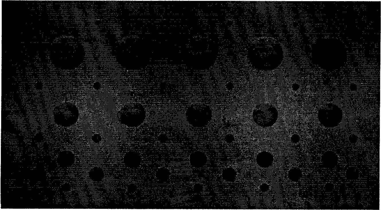
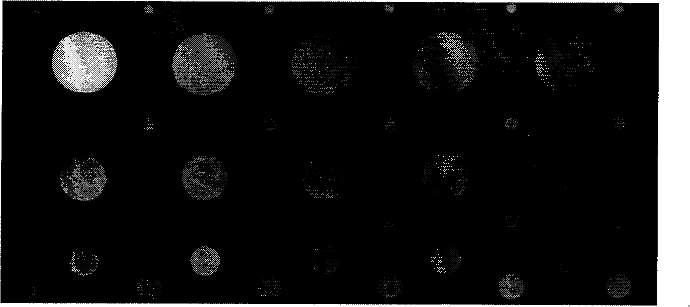
[0067] 1. Prepare a high-purity graphite plate with a size of 240mm*135mm*8mm. Blind holes of different depths and sizes are drilled on the graphite plate, and the blind holes are divided into 4 groups (see Figure 5 ), the diameters of each group of blind holes from top to bottom are: 20mm, 15mm, 10mm and 5mm; the depths of each group are: 7.5mm, 7.0mm, 6.5mm, 6.0mm and 5.5mm. Finally, the graphite defect standard sample was obtained.

[0068] 2. Use the X-ray photographic detection technology to detect the standard sample, and obtain the X-ray photographic film of the standard sample.

[0069] 3. Scan the negative film into an electronic picture to obtain its grayscale image (see Image 6 ), the second and third groups of corresponding defect regions are intercepted on the grays...

Embodiment 3

[0074] Example 3: Designing and preparing a two-dimensional stacked C / SiC material standard sample with blind hole defects with varying thickness.

[0075] refer to Figures 9 to 12 , the specific steps are:

[0076] 1. Select two-dimensional laminated carbon cloth as the prefabricated body, and cut it into a thin plate shape with a size of 240mm*135mm*8mm. The pyrolytic carbon interface layer was deposited on the preform, and the process conditions were as follows: deposition temperature: 800°C, pressure 0.2Kpa, propylene flow rate 35ml / min, Ar gas flow rate 250ml / min, and deposition time 60h.

[0077] The silicon carbide substrate was deposited on the two-dimensional laminated carbon cloth deposited with the pyrolytic carbon interface layer. The process conditions were: deposition temperature 800 °C, pressure 4KPa, H 2 Gas flow 150ml / min, Ar gas flow 250ml / min, trichloromethylsilane temperature 35°C, H 2 The molar mass ratio to MTS is 1:12, and the deposition time is 240h...


PUM


Abstract

The invention discloses a method for measuring defect thickness in carbon/silicon carbide composite material, comprising the following steps: a defect material sample, the thickness of which is changed in a way of gradient, is designed and prepared; a measuring sample is photographed by X-ray; a photoplate is scanned to be an electronic picture so that a gray level image thereof is obtained; ratio between the gray level of each defect area of the image and the gray level of no-defect area of the image is obtained by computing in a way of programming so as to establish a calibration function relational expression of the defect depth and the corresponding gray level ratio; and the defect thickness of the same material is computed with the calibration function under the same detecting condition to realize the quantitative measurement of the defect depth. The method conquers the defects of small detecting area, large error, low detecting efficiency, and the like, since the traditional X-ray photographing nondestructive detecting method detects the defect thickness with a nigrometer at one time, establishes the calibration function relationship of the ratio of the material defect thickness, the material defect gray level and the material no-defect gray level, realizes the quantitative measurement of the defect depth of the material, and has high detecting efficiency and higher precision.

Description

technical field [0001] The invention relates to a method for measuring the thickness of internal defects in composite materials, in particular to a method for measuring the thickness of internal defects in carbon / silicon carbide composite materials. Background technique [0002] As a mature non-destructive testing technology, X-ray radiography is widely used in the non-destructive testing and evaluation of various materials, parts and components. For the quantitative detection of defect thickness, the traditional X-ray photographic detection method is to use a blackness meter, that is, the blackness meter is used to measure the blackness value of the defect and non-defect area on the X-ray photographic film, and the material hole defect is calculated by the difference in blackness. thickness. However, this method has disadvantages such as the small measurement area of ​​the blackness meter at one time, that is, it can only achieve point measurement, the shape of the defect ...

Claims


Application Information

Patent Timeline
IPC IPC(8): G01B15/02G01N1/28
Inventor 梅辉成来飞邓晓东张立同王东赵东林陈曦
Owner NORTHWESTERN POLYTECHNICAL UNIV
Why Eureka
Try Eureka