Unlock instant, AI-driven research and patent intelligence for your innovation.

Voltage comparator

A voltage comparator and comparator technology, which is used in instruments, regulating electrical variables, multiple input and output pulse circuits, etc., can solve large static power consumption and dynamic power consumption, cannot further reduce costs, and increase chip effective area and other problems, to achieve the effect of reducing static power consumption and dynamic power consumption, reducing the effective area, and reducing the number of devices

Inactive Publication Date: 2012-06-13
深圳市展芯微电子技术有限公司
View PDF6 Cites 0 Cited by
  • Summary
  • Abstract
  • Description
  • Claims
  • Application Information

AI Technical Summary

Problems solved by technology

[0005] In the existing circuit technology, most of the voltage comparators used in power-on reset, overvoltage detection, undervoltage detection and other circuits use an independent bandgap reference voltage generation circuit to generate a reference voltage, and then through an independent comparison The current comparator compares the sampling voltage and the reference voltage, so the existing voltage comparator has large static power consumption and dynamic power consumption, and has a large number of devices, which increases the effective area of ​​the chip and cannot further reduce the cost.

Method used


Image

  • Voltage comparator
  • Voltage comparator
  • Voltage comparator

Examples


Embodiment Construction

[0034] In order to make the object, technical solution and advantages of the present invention more clearly, the present invention will be further described in detail below in conjunction with the accompanying drawings and specific embodiments.

[0035] At first, the technical term involved in the present invention is explained:

[0036] PMOS: P-channel metal oxide semiconductor FET, P-channel metal oxide semiconductor field effect transistor;

[0037] NMOS: N-channel metal oxide semiconductor FET, N-channel metal oxide semiconductor field effect transistor.

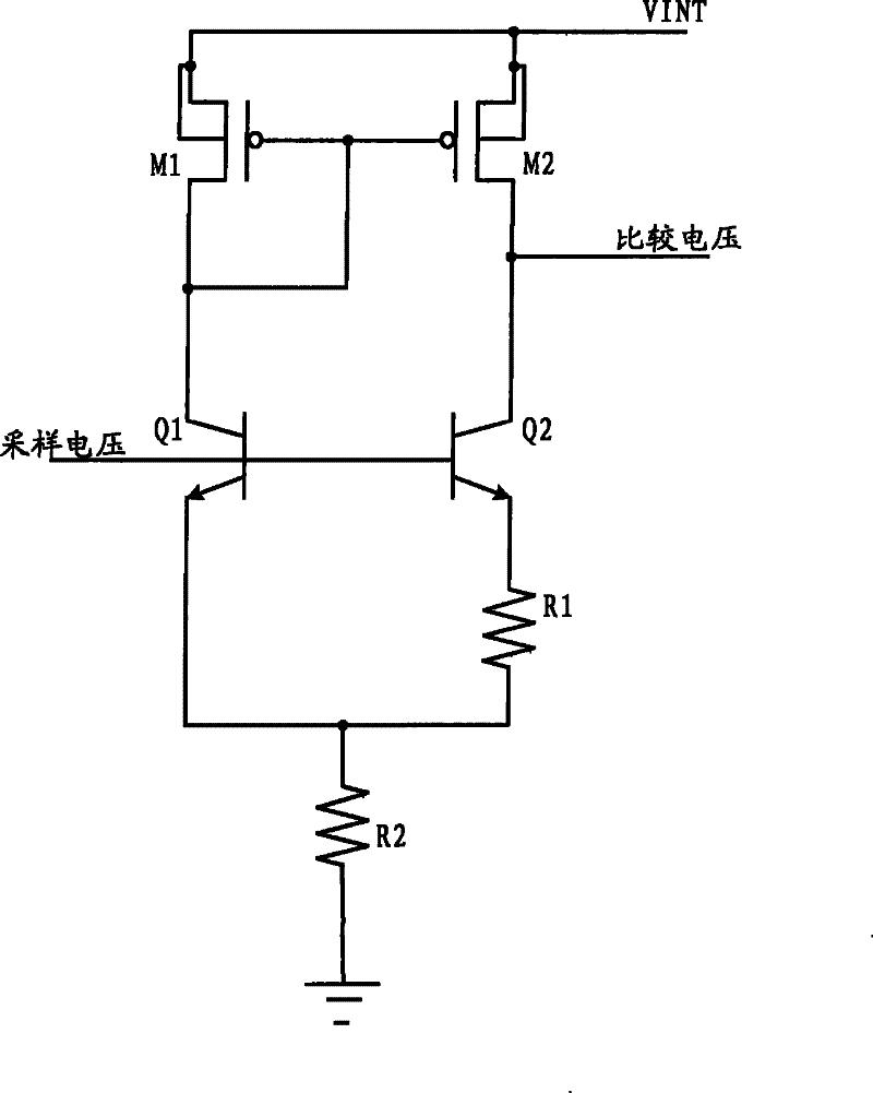
[0038] A voltage comparator of the present invention includes a composite circuit, the composite circuit has a built-in reference voltage source and a comparator, and the composite circuit is used to receive a sampling voltage and output a comparison voltage after comparing with an internal reference voltage.

[0039] refer to figure 1 , shows a circuit diagram of a composite circuit of a voltage comparator preferably ...


PUM


Abstract

The invention discloses a voltage comparator comprising a compound circuit. The compound circuit comprises a first PMOS tube, a second PMOS tube, a first NPN tube, a second NPN tube, a first resistor and a second resistor. Source electrodes of the first PMOS tube and the second PMOS tube are connected with power supply, a grid electrode and a drain electrode of the first PMOS tube are in a short circuit, and the grid electrode of the second PMOS tube is connected with the grid electrode of the first PMOS tube so as to form a current mirror; the drain electrode of the first PMOS tube is connected with a collector of the first NPN tube, the drain electrode of the second PMOS tube is connected with a collector of the second NPN tube, base electrodes of the first NPN tube and the second NPN tube are connected with sampling voltage, an emitter electrode of the second NPN tube is connected with a positive electrode of a third resistor, the emitter electrode of the first NPN tube is connectedwith a negative electrode of the third resistor, the positive electrode of a fourth resistor is connected with the negative electrode of the third resistor, and the negative electrode of the fourth resistor is grounded. A reference voltage source and the comparator are combined into one, thus reducing number of devices in the circuit, static power consumption and dynamic power consumption, and effective area of an integrated circuit chip.

Description

technical field [0001] The invention mainly relates to the field of analog integrated circuits, in particular to a voltage comparator with an internal self-built reference source. Background technique [0002] Integrated circuits (ICs) have grown from a handful of interconnected devices fabricated on a single silicon chip to millions of devices. Today's integrated circuits offer performance and complexity far beyond what was originally imagined. To achieve improvements in complexity and circuit density (ie, the number of devices that can be packed onto a given chip area), the minimum device feature size has evolved smaller with each generation of integrated circuits. [0003] Increasing circuit density not only improves the complexity and performance of integrated circuits, but also provides consumers with lower cost components. Integrated circuit equipment is worth hundreds of millions or even billions of dollars, each facility has a certain number of wafers, and each waf...

Claims


Application Information

Patent Timeline
Patent Type & Authority Patents(China)
IPC IPC(8): H03K5/24G05F1/56
Inventor 雷晗
Owner 深圳市展芯微电子技术有限公司