Single-tube suction dredge

A mud suction machine and single-pipe technology, which is applied to the feeding/discharging device of the sedimentation tank, etc., can solve the problems of difficult absolute balance of the rotating structure, muddy water disturbance in the sedimentation tank, increased energy consumption and wear, etc., and achieves the basic cost. The effect of increasing, less muddy water disturbance, and reducing the total weight of the main engine

Inactive Publication Date: 2009-10-21
广东新环环保产业集团有限公司
View PDF0 Cites 5 Cited by
  • Summary
  • Abstract
  • Description
  • Claims
  • Application Information

AI Technical Summary

Problems solved by technology

[0008] 5) The support truss has a disturbing effect on the muddy water in the sedimentation tank while balancing the suction pipe and supporting the skimming device, and the running resistance increases
[0009] 6) The skimming effect of the linear skimming device is not good
[0011] 8) The rotating structure is difficult to be absolutely balanced, and the unbalanced moment acts on the central slewing support to increase energy consumption and wear
[0012] 9) It is not suitable to be used in primary sedimentation tanks with high sludge concentration and large sedimentation tanks over 50 meters

Method used


Image

  • Single-tube suction dredge
  • Single-tube suction dredge

Examples


Embodiment 1

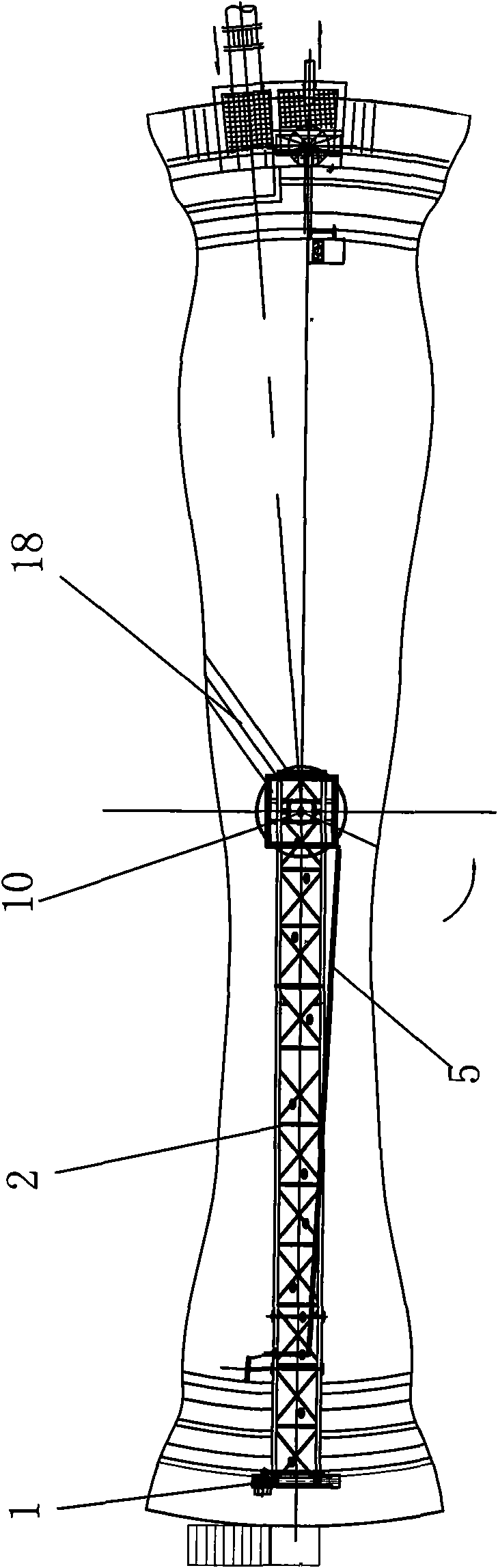
[0026] Example 1, such as figure 1 and figure 2 Shown: a single-pipe dredger, including a dredging pipe 4 arranged inside and outside the bottom of the sedimentation tank through a sealing cylinder 9 movable and sealed connection, a bridge device installed in the sedimentation tank to pull the dredging pipe 4, the sealing cylinder 8 and drive unit 1. The suction pipe 4 rotates around the center of the sedimentation tank at the bottom of the sedimentation tank. The bridge device includes a central column 7 in the fixed sedimentation tank, a central turntable 6, a working bridge 2, a central vertical frame 8, and a suction pipe pull rod 3. The central turntable 6 is movably connected to the center column 7 to form a slewing support, and the turntable is equipped with a current collector, and its upper and lower rings are respectively connected with the poolside motor cable and the central pre-embedded cable. The central turntable 6 is connected to the working bridge 2, and t...

Embodiment 2

[0027] In Embodiment 2, in order to scrape the scum on the pool surface to the scum discharge barrel and discharge it, a bridge hanging scum skimming device 5 is also installed on the working bridge 2, and the bridge hanging scum skimming device is a long baffle. All the other are with embodiment 1.

[0028] Further, the driving device is an electric trolley; the driving device 1 drives the working bridge 2 to rotate around the center column 7, and pulls the bridge hanging skimming device directly connected to the working bridge, the suction pipe pull rod, the suction pipe, and the center vertical frame And the sealing cylinder rotates.

[0029] The liquefaction plate inclined at 45 degrees between the bottom of the suction pipe 4 and the bottom of the pool is parallel to the long beam of the working bridge. There is a liquefaction plate inclined at 45 degrees between the suction pipe and the bottom of the pool, which can completely suck away even the inert sludge with a larg...


PUM


Abstract

The invention discloses a single-tube suction dredge, comprising a dredging tube which is arranged at the bottom of a sedimentation tank and is movably connected and communicated at the inside and outside thereof by a sealing cylinder in a sealing manner, a traction arranged, a bridging device which is arranged in the sedimentation tank and tows the dredging tube and the sealing cylinder, and a driving device. The bridging device comprises a central column, a central rotating disc, a working bridge, a central vertical frame and a pulling rod of the dredging tube which are fixed in the sedimentation tank; the central rotating disc is movably coupled with the central column to form a revolving support and is coupled with the working bridge and the central vertical frame outside of the central column. A skimming device is coupled below the working bridge; one end of the working bridge is coupled with the central column by the central rotating disc movably and the other end thereof is coupled with the driving device and travels along the edge of the tank; the working bridge is fixedly connected with the dredging tube by the pulling rod of the dredging tube; and the central vertical frame is fixed coupled with the working bridge and the sealing cylinder. As the periphery is adopted to drive the dredging tube, the single-tube suction dredge has simplified structure, less disturbance to muddy water, good skimming effect, light weight for a main machine and low cost, and is particularly applicable to the primary sedimentation tank with larger sewage sludge concentration and the large sedimentation tank of more than 50m.

Description

technical field [0001] The invention relates to an automatic sludge discharge mechanical device installed in a radial flow sedimentation tank in the environmental protection fields such as water treatment, domestic sewage treatment, and industrial wastewater treatment. In particular, it relates to a single-pipe dredge suction machine for radial flow circular sedimentation tanks. Background technique [0002] In water treatment, domestic sewage treatment, industrial wastewater treatment and other environmental protection fields, an economical and applicable way to treat raw water is to put it in a sedimentation tank for sedimentation, and then put the reclaimed water after sedimentation on the surface of the pool Drain for another treatment or use directly. A very important link in this treatment method is to discharge the sediment that settles to the bottom of the tank during the sedimentation process, that is, the so-called sludge. In the prior art, mechanical equipment su...

Claims


Application Information

Patent Timeline
Patent Type & Authority Applications(China)
IPC IPC(8): B01D21/24
Inventor 黎庆辉程鉴昌张新陈志敏刘凯俊
Owner 广东新环环保产业集团有限公司
Why Eureka
Try Eureka