Method and device for polishing magnetic field auxiliary flexible rotary brush for optical element

A magnetic field-assisted, optical element technology, applied in polishing compositions containing abrasives, optical surface grinders, grinding/polishing equipment, etc., can solve the problem that the quality of the machined surface and the stability of the removal function and the computer control ability are not high. Accurate optical processing, inability to meet the needs of conformal optical inner concave processing, etc., to achieve the effect of compact structure and high removal efficiency

Inactive Publication Date: 2009-10-21
TSINGHUA UNIV
View PDF0 Cites 49 Cited by
  • Summary
  • Abstract
  • Description
  • Claims
  • Application Information

AI Technical Summary

Problems solved by technology

This method is currently only limited to the grinding process, and its surface quality, stability of the removal function, and computer control capabilities cannot meet the requirements of high-precision optical processing.
At the same time, the currently available forms of action cannot meet the processing requirements of conformal optical inner concave surfaces.

Method used


Image

  • Method and device for polishing magnetic field auxiliary flexible rotary brush for optical element
  • Method and device for polishing magnetic field auxiliary flexible rotary brush for optical element
  • Method and device for polishing magnetic field auxiliary flexible rotary brush for optical element

Examples


Embodiment 1

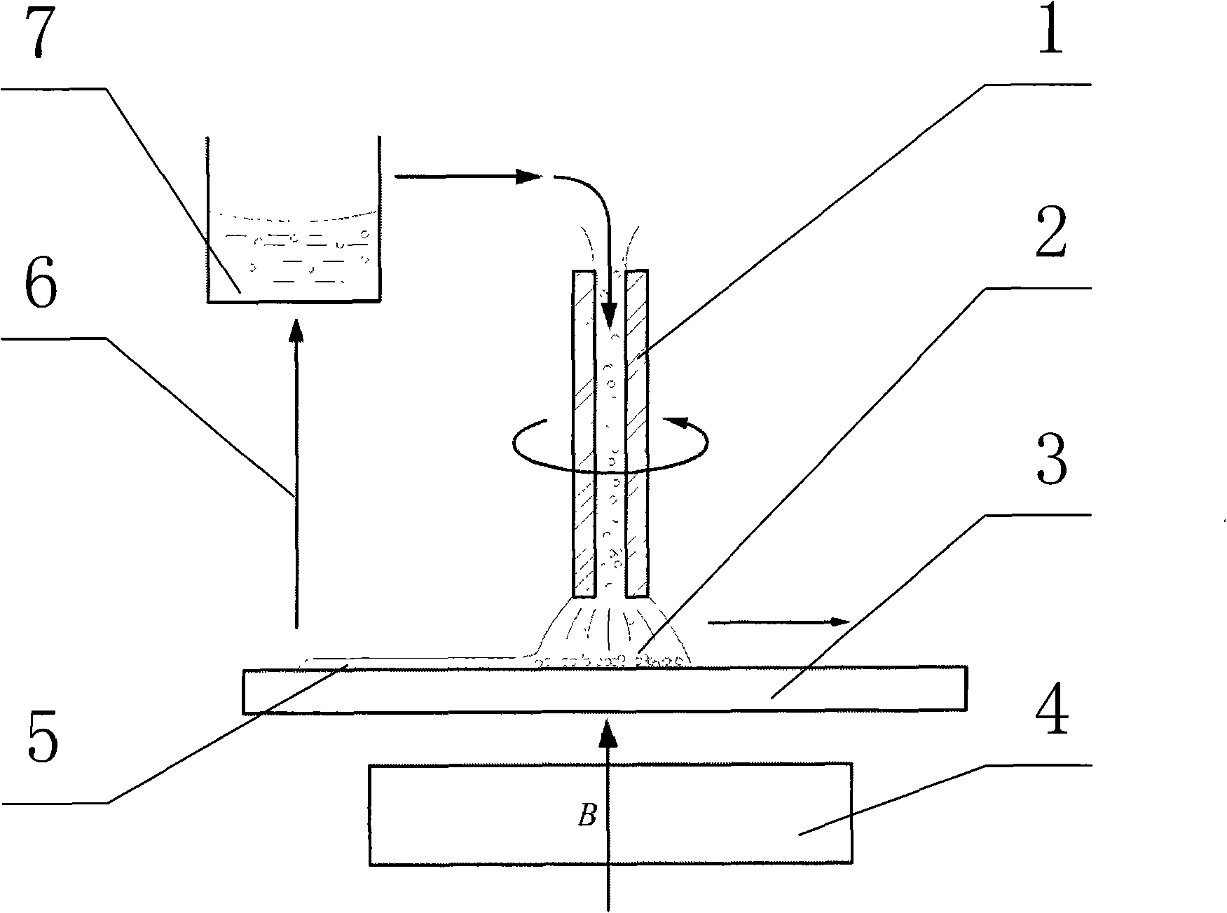
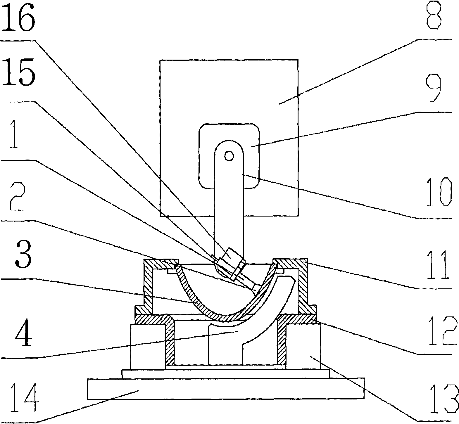
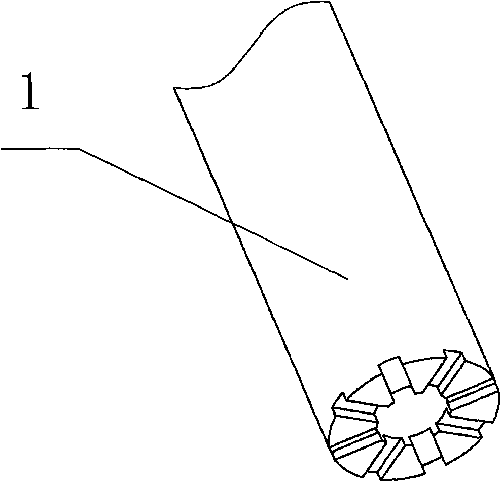
[0032] figure 2 It is a schematic diagram of the structure of the device for polishing the inner concave surface of the optical element of the present invention. The polishing turntable base 13 is fixedly connected with the CNC XY workbench 14, the polishing turntable 12 is installed on the polishing turntable base 13, and has a center hole; the excitation pole 4 in the form of a permanent magnet passes through the center hole of the turntable and is fixedly connected with the CNC XY workbench 14 , the workpiece 3 is installed upside down and fixed on the workpiece fixture 11, the workpiece fixture 11 is fixedly connected with the polishing turntable 12, and keeps the symmetry axis of the workpiece 3 and the center of rotation of the polishing turntable 12 coincident; the polishing spindle 1 is made of carbon steel material, with a diameter of 5mm, and driven by the spindle driver 16; the spindle driver 16 is a micro DC motor, using gear transmission; the polishing spindle 1 ...

Embodiment 2

[0040] In this embodiment, the excitation pole 4 is in the form of an electromagnet, and the magnetic field intensity in the processing area can be further controlled by current. The device structure and processing method of other parts are the same as in Embodiment 1.

Embodiment 3

[0042] In this embodiment, the main shaft driver 16 is driven by a flexible shaft, and the flexible shaft is driven by an external motor to obtain higher rotational speed and driving torque. The device structure and processing method of other parts are the same as those in Example 1.


PUM

PropertyMeasurementUnit
particle sizeaaaaaaaaaa

Abstract

The invention belongs to the technical field of precise optical polishing processing, and in particular relates to a method and a device for polishing a magnetic field auxiliary flexible rotary brush for an optical element. The method comprises that a ferromagnetic main shaft capable of rotating at a high speed drives a magnetorheological fluid which can be updated circularly to be adsorbed on a finished surface under certain pressure and the action of a magnetic field to form a flexible rotary polishing grinding head which finishes the polishing processing of a whole concave surface in a composite motion mode of self rotation and workpiece rotation. The device is applicable to polishing the concave surface of a conformal optical element; and the method has the characteristic of flexible fine machining and stable polishing removal, can adopt a computer to control the polishing removal distribution, is capable of controlling a polished surface shape, has the advantages of high precision and high surface quality, and is applicable to polishing aspheric surface and free-form surface elements with thin-walls and high gradients.

Description

technical field [0001] The invention belongs to the technical field of precision optical polishing, and in particular relates to a magnetic field-assisted flexible rotating brush polishing method and device for optical elements. Background technique [0002] With the development of optical design and processing technology, aspheric and free-form optical components are more and more widely used. Typical ones include conformal optical dome, conformal infrared detection window, picture tube correction lens, etc. This type of optical element has the property of high-steep aspheric surface or free-form surface, so that it can meet the special requirements of aerodynamics or structure while taking on the role of the optical system. However, in addition to bringing performance advantages, conformal optical elements bring many problems and challenges in terms of processing. Traditional optical fairings and windows mostly adopt the form of concentric spherical surfaces or plane spli...

Claims


Application Information

Patent Timeline
Patent Type & Authority Applications(China)
IPC IPC(8): B24B13/00B24B57/02C09G1/02
Inventor 冯之敬左巍辛科张云
Owner TSINGHUA UNIV
Why Eureka
Try Eureka