
Composite temperature cold treatment process

A composite temperature and cold treatment technology, applied in the field of heat treatment of metal materials, can solve the problems such as the inability to significantly reduce the amount of retained austenite, the time of microstructure transformation, and the large temperature difference between the surface of the workpiece core, so as to avoid macro cracks and reduce Retained austenite, effect of increasing hardness

Inactive Publication Date: 2009-10-21
上海市机械制造工艺研究所有限公司
View PDF0 Cites 25 Cited by
  • Summary
  • Abstract
  • Description
  • Claims
  • Application Information

AI Technical Summary

Problems solved by technology

[0004] However, the current heat treatment processes have certain limitations. Process (1) only reduces retained austenite through cold treatment. Process (2) not only achieves the purpose of process (1), but also due to cryogenic treatment or cryogenic treatment + low temperature tempering treatment, the precipitation of ultra-fine carbides can significantly improve the wear resistance of the material
However, quenching and subsequent cryogenic treatment make the material have larger residual stresses of the second and third types, forming more microcracks, resulting in a decrease in impact toughness, and at the same time, it is easy to cause a large temperature difference between the core and the surface of the workpiece. The time of tissue transformation is different, forming macroscopic cracks
Process (3) After quenching, low-temperature tempering is performed first to reduce the residual stress of the material, and then cryogenic treatment is performed to achieve the above purpose. However, for high-carbon alloy steel, low-temperature tempering after quenching produces residual austenite The body is stable, and the subsequent cryogenic treatment cannot significantly reduce the amount of retained austenite, and the increase in hardness is also very small

Method used


Image

  • Composite temperature cold treatment process

Examples


Embodiment Construction

[0033] 20mm with GCr15 material 3 The sample is example, carry out following embodiment:

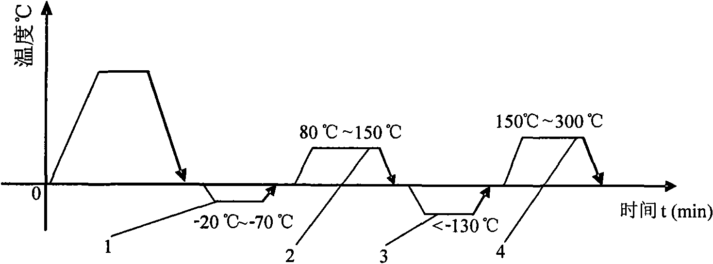
[0034] GCr15 is quenched first, and immediately after quenching, cold treatment is performed. The temperature of cold treatment is -20°C to -70°C, and the time is 60 minutes. It is warmed up in the air. After reaching room temperature, the first low-temperature tempering is performed, and the temperature is 80°C ~150℃, the time is 60 minutes, cool in the air, after reaching room temperature, carry out cryogenic treatment, the temperature is -180℃~-130℃, the time is 60 minutes, then return to the temperature in the air, after reaching room temperature, carry out the second Secondary low-temperature tempering, the temperature is 150 ℃ ~ 300 ℃, the time is 120 minutes, and then cooled in the air. As a result of the treatment, the hardness is 60-64HRC.

[0035] The following table is the following table for the hardness performance of the workpiece after each embodiment specific parameter a...


PUM


Abstract

The invention discloses a composite temperature cold treatment process, which comprises quenching and subsequent cold treatment. The process comprises the following steps: (1) performing quenching treatment on a steel part first; (2) performing the cold treatment immediately after the quenching at a temperature of between 20 DEG C below zero and 70 DEG C below zero until the center of the steel part is stone-cold; (3) performing lonneal for the first time at a temperature of between 80 and 150 DEG C; (4) performing sub-zero treatment at a temperature of less than 130 DEG C below zero until thecenter of the steel part is stone-cold; and (5) performing the lonneal for the second time. The composite temperature cold treatment process performs composite temperature cold treatment after the quenching, thus the process not only reduces retained austenite, stabilizes the size, increases the hardness, separates out superfine micro carbide and improves the wear resistance, but also effectivelycontrols the second type and the third type residual stresses of workpieces, greatly improves the impact toughness and avoids defects of macrocracks and the like because one time of the cold treatment and the lonneal are performed before the sub-zero treatment.

Description

technical field [0001] The invention relates to a heat treatment process for metal materials, in particular to a cold treatment process for high-carbon alloy steel after quenching. Background technique [0002] After the steel parts are quenched, a certain amount of retained austenite will be retained. The retained austenite is an unstable phase and will be transformed into martensite in the subsequent processing or service process, which will affect the dimensional stability of the workpiece. room temperature to -70°C) to reduce the amount of retained austenite and increase the hardness. Cryogenic treatment (<-130°C) can not only achieve the purpose of cold treatment, but also further reduce the amount of retained austenite, and precipitate ultrafine carbides, which can significantly improve the wear resistance of the material. [0003] In the prior art, there are three kinds of processes involving cold treatment of high-carbon low-alloy steel, (1) quenching + cold trea...

Claims


Application Information

Patent Timeline
IPC IPC(8): C21D1/78C21D6/00
Inventor 叶俭李斌石江龙卢军
Owner 上海市机械制造工艺研究所有限公司
Learn More