External gas removing type heat-storage incinerator

An incinerator and heat storage technology, applied in incinerators, lighting and heating equipment, combustion methods, etc., can solve the problems of pollution switching peak, pollution practical occasions, inconvenience, etc., and achieve the effect of improving ambient air quality and preventing pollution.

Inactive Publication Date: 2009-10-21
DESICCANT TECH CORP
View PDF0 Cites 9 Cited by
  • Summary
  • Abstract
  • Description
  • Claims
  • Application Information

AI Technical Summary

Problems solved by technology

In the known regenerative incinerator 10a, when the inlet and outlet valves of the double-tower incinerator switch the direction of airflow during the operation cycle, a peak emission equivalent to the inlet concentration will be generated to the chimney (exhaust port). Due to the destruction of the organic waste gas by the incinerator The efficiency can reach more than 98%, and the inlet airflow will be directly discharged to the chimney when switching. Based on the 98% destruction efficiency estimate, it can be known that the concentration can reach 50 times higher than the exhaust gas treated by the incinerator, which has always caused the industry The disadvantage of the known regenerative incinerator is that when the air flow direction of the valve is switched, a pollution switching peak will be generated, and the lack of pollution makes it inconvenient and troublesome in practical applications

Method used


Image

  • External gas removing type heat-storage incinerator
  • External gas removing type heat-storage incinerator
  • External gas removing type heat-storage incinerator

Examples


Embodiment Construction

[0081] Other characteristics and specific embodiments of the present invention can be further understood in the following detailed description with accompanying drawings.

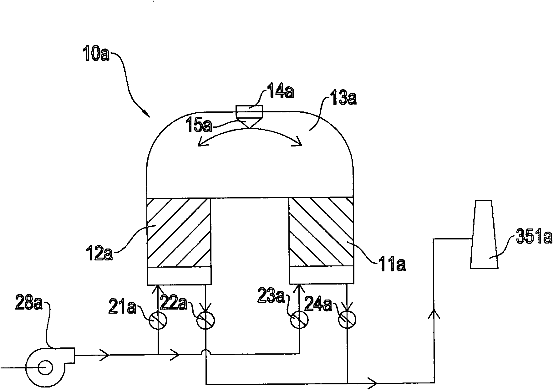
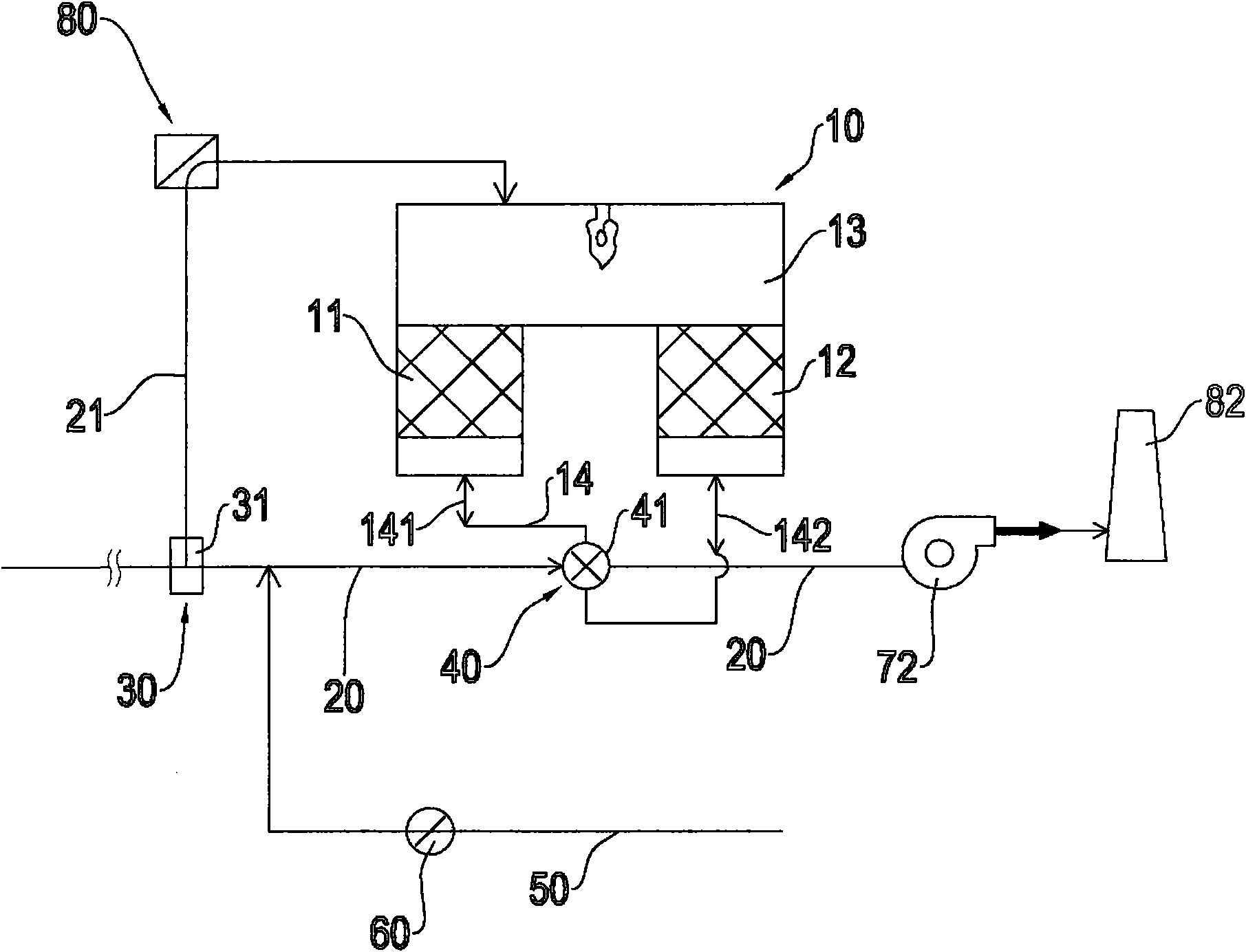
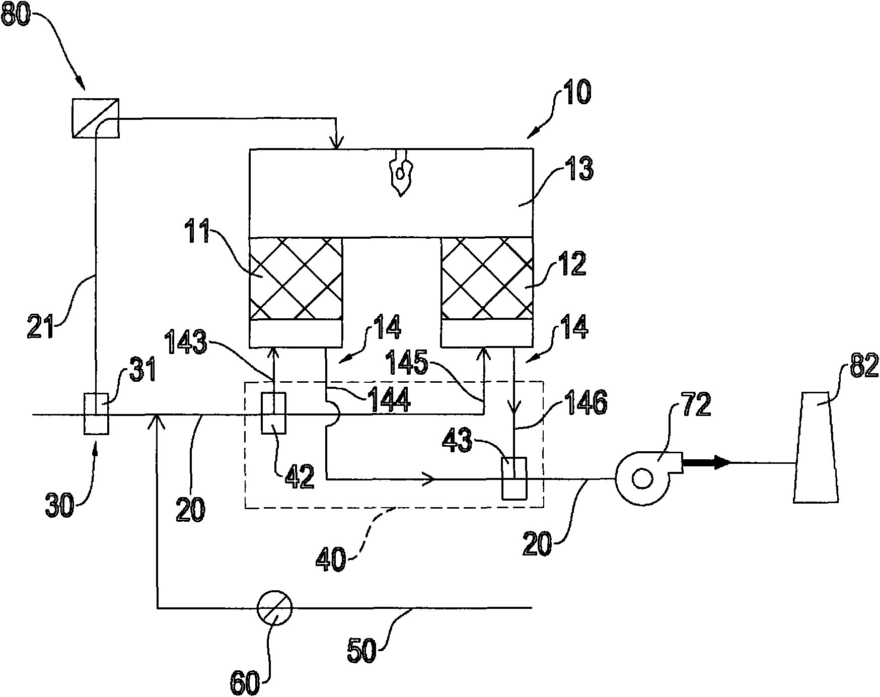
[0082] Please refer to figure 2 As shown, it is a schematic structural view of the external gas removal type regenerative incinerator of the present invention, which includes a regenerative incinerator 10, a main exhaust gas pipeline 20, a windmill 72, an exhaust gas inlet valve group 30, and a leading control valve group 40. An external air supply pipeline 50 and an external air control valve 60; the regenerative incinerator 10 is provided with a first heat storage bed 11, a second heat storage bed 12 and a combustion chamber 13, the combustion chamber 13 The space communicated with the top of the first heat storage bed 11 and the second heat storage bed 12, and the first heat storage bed 11 and the second heat storage bed 12 are respectively provided with at least one ventilation pipeline 14 (the first v...


PUM


Abstract

The invention relates to an external gas removing type heat-storage incinerator which comprises a heat-storage incinerator, an exhaust gas main pipeline, a windmill, an exhaust gas inlet valve bank, a leading control valve bank, an external gas blast pipeline and an external gas control valve, wherein the exhaust gas main pipeline is connected with a ventilating pipeline of the heat-storage incinerator, the exhaust gas inlet valve bank and the leading control valve bank are arranged on the exhaust gas pipeline so as to control and switch the pipeline to control the flow direction of the exhaust gas in the pipeline, the tail end of the exhaust gas main pipeline is provided with the windmill to form wind pressure to suck the gas in the pipeline, one end of the external gas blast pipeline is connected with the exhaust gas main pipeline to supply gas into the exhaust gas main pipeline and a heat-storage bed, the external gas control valve is arranged on the external gas blast pipeline to control the ingress and the egress of the external gas, therefore, when the heat-storage incinerator switches a gas flowing direction, the external gas blast pipeline is controlled to supply gas, and the high-concentration pollution of the heat-storage incinerator for switching the gas flow directions of two towers is eliminated to remove the exhaust gas pollution.

Description

technical field [0001] The present invention relates to a regenerative thermal incinerator for removing external air, in particular to a regenerative thermal oxidizer (RTO). , a waste gas inlet valve group, a leading control valve group, an external air supply pipeline and an external air control valve, which can make the regenerative combustion furnace switch the direction of the airflow when switching the direction of the airflow. Another function is that the unburned waste gas of the heat storage bed will not leak out, and the pollution peak of the operation will be generated to achieve the function of stable utilization. It is suitable for industries that need to reduce the generation of organic waste gas, such as some The production field of a specific industry, such as semiconductor industry, optoelectronic industry, chemical industry, etc. Background technique [0002] Volatile organic compounds (Volatile Organic Compound, VOC) are widely used in the industry, and ar...

Claims


Application Information

Patent Timeline
Patent Type & Authority Applications(China)
IPC IPC(8): F23G7/06
Inventor 郑石治扶亚民田磊徐瑞珠刘邦昱洪守铭
Owner DESICCANT TECH CORP
Why Eureka
Try Eureka