Method for producing semiconductor packaging part

A semiconductor and packaging technology, applied in the field of flip-chip semiconductor packaging manufacturing, can solve the problems of tool wear, increase manufacturing cost and complexity, reduce waste, improve product yield, and reduce tool wear. Effect

Active Publication Date: 2009-10-21
SILICONWARE PRECISION IND CO LTD
View PDF2 Cites 9 Cited by
  • Summary
  • Abstract
  • Description
  • Claims
  • Application Information

AI Technical Summary

Problems solved by technology

[0008] However, in the aforementioned manufacturing method, not only an interface layer needs to be added to increase the manufacturing cost and complexity, but also the cutting path of the cutting tool will pass through the heat sink during the cutting operation, resulting in severe tool wear

Method used


Image

  • Method for producing semiconductor packaging part
  • Method for producing semiconductor packaging part
  • Method for producing semiconductor packaging part

Examples


no. 1 example

[0063] see Figure 3A to Figure 3G , is the first embodiment of the manufacturing method of the semiconductor package proposed by the present invention.

[0064] Such as Figure 3A As shown, a carrier 30 is provided, and the carrier 30 has a plurality of openings 300 thereon. The carrier 30 is made of organic insulating materials such as FR4, FR5, BT and the like.

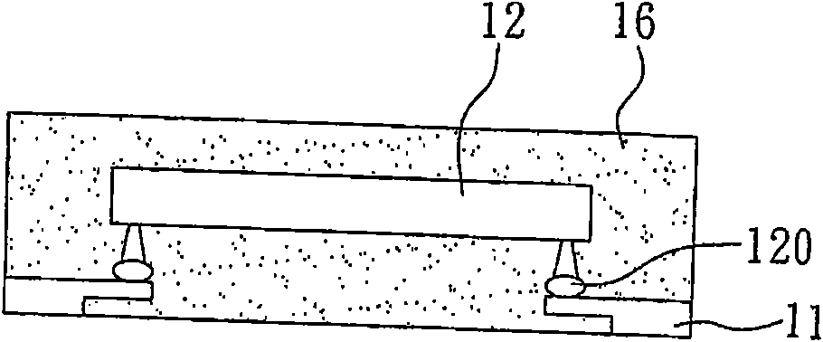
[0065] Such as Figure 3B As shown, a plurality of substrates 31 are provided for the flip-chip semiconductor chips 32 to be connected and electrically connected to the substrates 31 through conductive bumps 320, and the flip-chip semiconductor chips 32 are connected with The heat sink 33 , wherein the length and width of the substrate 31 are approximately equal to the predetermined length and width of the semiconductor package to be completed, and the length and width of the heat sink 33 are smaller than the length and width of the substrate 31 .

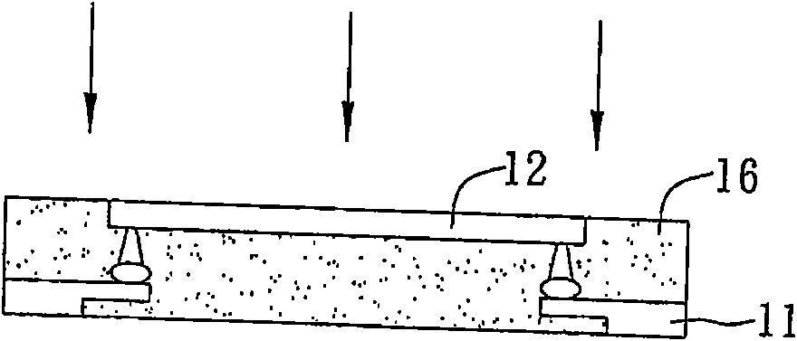
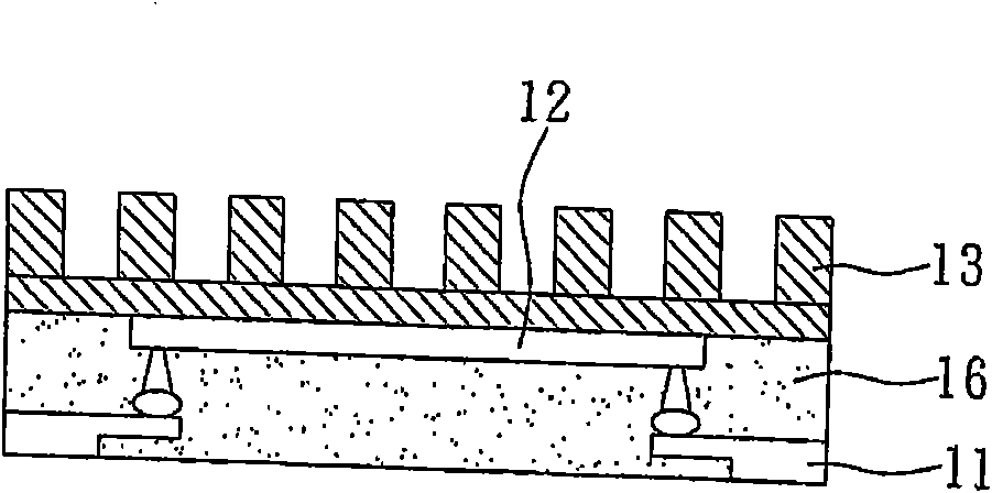
[0066] Such as Figure 3C As shown, the plurality of substrat...

no. 2 example

[0078] see Figure 4A to Figure 4E , is a schematic diagram of the second embodiment of the manufacturing method of the semiconductor package of the present invention.

[0079] In addition to selecting organic insulating materials such as FR4, FR5, BT, etc., the carrier of the present invention can also use a metal material coated with a metal coating on the surface. The metal coating is a coating material that is not easy to adhere to the packaging colloid. In this embodiment The predetermined length and width dimensions of the semiconductor package, the preparation dimensions of the substrate, the flip-chip semiconductor chip and the heat sink, and the opening dimensions of the carrier are all similar to those of the aforementioned first embodiment, and the main difference is that the carrier The selection of materials and some process steps.

[0080] Such as Figure 4A As shown, a carrier 40 is prepared, and the carrier 40 has a plurality of openings 400, wherein the carr...


PUM


Abstract

The invention relates to a method for producing a semiconductor packaging part, adopting a plurality of substrates and a bearing part provided with multiple openings, wherein flip-chip semiconductor chips and radiating pieces are sequentially arranged on each substrate, the size of each substrate is approximately equal to the predetermined size of a packaging part, and the size of each radiating piece is smaller than the size of each substrate so as to position the substrates in the openings of the bearing part; then packaging colloids used for covering the chips and the radiating pieces are formed on the openings, wherein areas covered by the packaging colloids are larger than the size of the openings, the step of demoulding is carried out, and laser is utilized for eliminating the packaging colloids which cover the radiating pieces; the operation of cutting is carried out along the edges of the substrates to produce a plurality of semiconductor packaging parts, thereby enabling the packaging colloids to directly cover the inverted chip type semiconductor chips and the radiating pieces; and besides, the laser is utilized for eliminating the packaging colloids on the upper parts of the radiating pieces so as to effectively disperse the heat amount of the chips, to prevent the problem of chip damage caused by the packaging colloid elimination by the existing mode of mechanical abrasion or chemical etching, and to reduce the problem of abrasion of a cutting tool which passes through the radiating pieces.

Description

technical field [0001] The invention relates to a method for manufacturing a semiconductor package, in particular to a method for manufacturing a flip-chip semiconductor package. Background technique [0002] Flip-Chip Ball Grid Array (FCBGA) semiconductor package is a packaging structure with flip chip and ball grid array at the same time, so that the active surface (Active Surface) of at least one chip can pass through A plurality of bumps (Solder Bumps) are electrically connected to one surface of the substrate (Substrate), and a plurality of solder balls (Solder Balls) as input / output (I / O) terminals are planted on the other surface of the substrate. ); this packaging structure can greatly reduce the volume, and at the same time save the design of the existing wire (Wire), and can reduce the impedance and improve the electrical properties, so as to avoid the degradation of the signal during the transmission process, so it has indeed become the next generation of chips an...

Claims


Application Information

Patent Timeline
Patent Type & Authority Applications(China)
IPC IPC(8): H01L21/50H01L21/56H01L21/78
CPCH01L21/565H01L21/568H01L24/97H01L2224/16225H01L2224/16245H01L2224/32225H01L2224/32245H01L2224/4824H01L2224/73215H01L2224/73253H01L2224/73265H01L2224/97H01L2924/15311H01L2924/181H01L2224/83H01L2224/85H01L2224/81H01L2924/00
Inventor 洪敏顺蔡和易萧承旭
Owner SILICONWARE PRECISION IND CO LTD
Why Eureka
Try Eureka