twin scroll combustor

A combustion chamber and flame tube technology, applied in the field of double vortex combustion chamber, can solve the problems of insufficient uniformity of fuel concentration field distribution, insufficient residence time, unfavorable formation of stagnant vortices, etc., so as to improve the distribution of fuel concentration field and omit the cooling air flow path. , the effect of reducing weight

Inactive Publication Date: 2011-12-07
BEIHANG UNIV
View PDF3 Cites 0 Cited by
  • Summary
  • Abstract
  • Description
  • Claims
  • Application Information

AI Technical Summary

Problems solved by technology

A gas turbine engine combustor barrel assembly introduced in the publication number CN1467407A adopts fuel and air premixed gas; the mainstream does not adopt a diffuser structure, which limits the flow rate of the mainstream to a certain extent, and adopts a petal-type support plate structure, which increases the weight
In application number 5791148, application date Aug, 11,1998, the trapped vortex combustor introduced in the LINER OF A GAS TURBINE ENGINE COMBUSTOR HAVING TRAPPED VORTEX CAVITY (the gas turbine combustor using the trapped vortex concave cavity) is applied to the main combustion chamber of the aero-engine In the design, the mainstream adopts the oil injection rod to supply oil, which is heavy; the support plate diffuser structure is adopted, which is heavy; the oil supply of the concave cavity and the air intake hole adopt a surrounding structure, which is not conducive to the formation of the standing vortex
In the single-vortex combustion chamber introduced in the publication number CN101070961A, a baffle plate structure is adopted on the concave cavity, which increases the weight; the single-vortex structure formed in the concave cavity makes the distribution of the fuel concentration field not uniform enough, and the residence time of its combustion in the concave cavity is not enough long, which limits the further improvement of combustion performance to a certain extent

Method used


Image

  • twin scroll combustor
  • twin scroll combustor
  • twin scroll combustor

Examples


Embodiment Construction

[0041] The present invention will be further described in detail below in conjunction with the accompanying drawings.

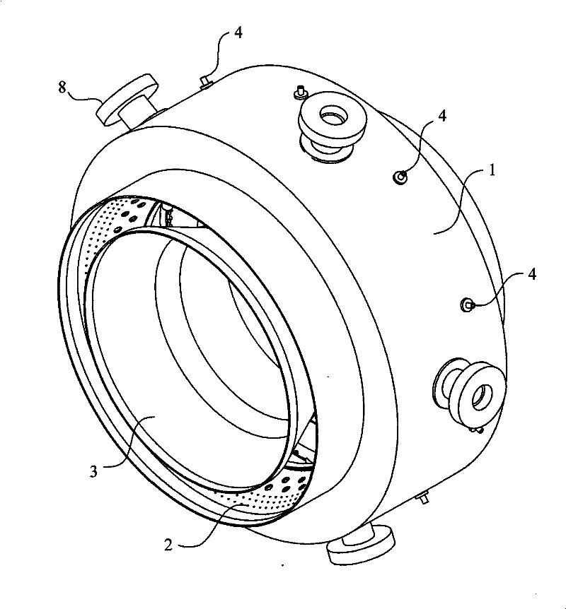
[0042] The present invention is a twin-scroll combustor, such as figure 1 As shown, it includes a shell 1, an outer flame tube 2 and an inner flame tube 3. Five ignition seats 8 and ten fuel injection pipes 4 are evenly arranged in the circumferential direction of the housing 1 .

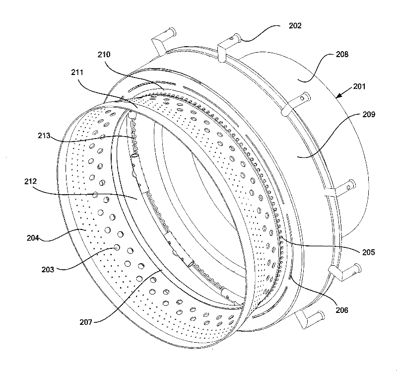
[0043] Such as figure 2 As shown, the outer layer flame tube base 201 is divided into four sections, namely the first section 208 of the outer layer flame tube base body, the second section 209 of the outer layer flame tube base body, the third section 210 of the outer layer flame tube base body, and the outer layer flame tube base body. The fourth section 211 of the flame cylinder substrate.

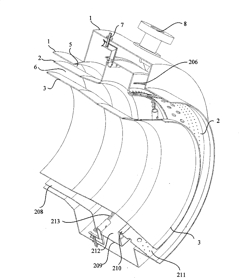
[0044] Such as figure 2 and image 3 As shown, the outer wall of the inner flame tube 3 and the inner wall of the outer flame tube 2 form a combustion channel 6 for combustion of the ...


PUM


Abstract

The invention discloses a double-vortex combustion chamber, which adopts a full-ring flame tube structure, including a shell, an inner layer and an outer layer flame tube, and the outer wall of the outer layer flame tube and the inner wall of the shell form a cooling cavity channel; the inner wall of the outer layer flame tube and the The outer wall of the inner flame tube forms the combustion channel; the fuel injection pipe and the ignition seat are evenly arranged in the circumferential direction of the shell; Two rows of front air holes are arranged on the edge of the wall, and the evaporation tube extends into the cavity along the circumferential direction of the cavity and close to the inner surface of the front wall of the cavity, and there is a rear air intake groove at half the height of the rear wall of the cavity; Air film cooling intake holes and air film cooling intake hole baffles are arranged in the third section; mixing holes and divergent cooling holes are opened in the fourth section; the double scroll structure formed in the concave cavity of the double scroll combustion chamber of the present invention improves the fuel consumption. The concentration field distribution realizes staged combustion, increases the residence time of fuel combustion, reduces the emission of pollutants, and makes the outlet temperature more uniform.

Description

technical field [0001] The invention relates to a twin-scroll combustion chamber, which belongs to the field of engines. Background technique [0002] The combustion chamber is an important part of the engine where fuel is burned, converting chemical energy into heat. A good combustion chamber should have the basic characteristics of good ignition performance, uniform temperature distribution, small flow resistance loss, less exhaust pollution and compact structure. [0003] The traditional aircraft engine combustor head mainly adopts the combination configuration of swirler and nozzle. After the air passes through the swirler, a recirculation zone is generated, and the high-temperature combustion products flow to the front end under the action of the recirculation zone, igniting the mixture of fresh fuel and air, and the recirculation zone acts as a stable ignition source. Trapped vortex combustor (TVC for short), which abandons the traditional combustion chamber design o...

Claims


Application Information

Patent Timeline
Patent Type & Authority Patents(China)
IPC IPC(8): F23R3/58F23R3/06F23R3/32
Inventor 张荣春樊未军宋双文宋玄进杨茂林
Owner BEIHANG UNIV
Why Eureka
Try Eureka