Method for establishing depth of field data for three-dimensional image and system thereof

A technology of stereoscopic image and establishment method, which is applied in the field of field depth data establishment of stereoscopic image and its system field, can solve the problems of time-consuming, limited sensing distance of infrared sensor, inability to obtain field depth data or depth of field signal, etc., to expand the practical range, improve The effect of compositing effects

Inactive Publication Date: 2009-10-28
CHUNGHWA PICTURE TUBES LTD
View PDF0 Cites 5 Cited by
  • Summary
  • Abstract
  • Description
  • Claims
  • Application Information

AI Technical Summary

Problems solved by technology

[0006] However, using virtual reality software to create a three-dimensional scene and then shoot, it is necessary to design the virtual scene and shoot and produce 3D three-dimensional animation, which is very time-consuming and cannot be applied to the shooting of actual objects (including human bodies or objects)
[0007] Secondly, if two images from different perspectives are taken for the same scene, and then synthesized into a stereoscopic image, the viewer can feel the three-dimensionality of the object from this stereoscopic image, but this kind o

Method used


Image

  • Method for establishing depth of field data for three-dimensional image and system thereof
  • Method for establishing depth of field data for three-dimensional image and system thereof
  • Method for establishing depth of field data for three-dimensional image and system thereof

Examples


Embodiment Construction

[0042] In order to have a further understanding of the terminal point, structural features and functions of the present invention, the relevant embodiments and drawings are described in detail as follows:

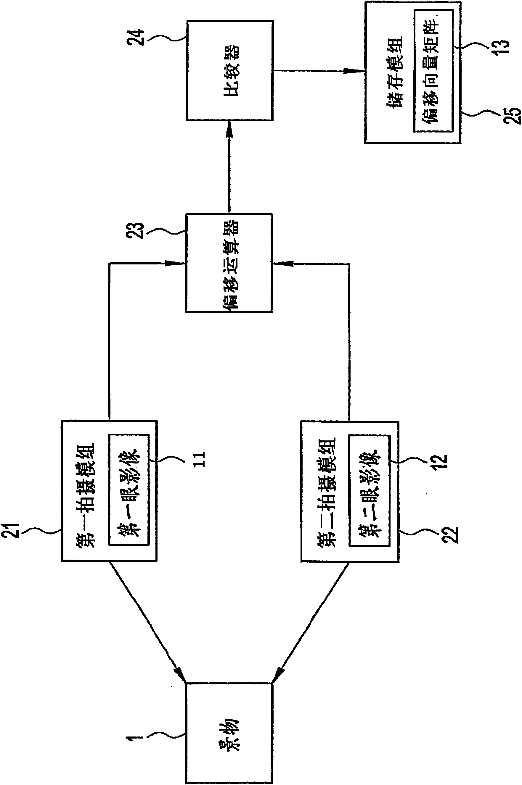
[0043] Please refer to figure 1 , which is an example of a system block diagram of the present invention, the system includes a first imaging module 21 , a second imaging module 22 , a storage module 25 , an offset calculator 23 and a comparator 24 .

[0044] The first imaging module 21 photographs a scene 1 to generate a first-eye image 11 , and the second imaging module 22 photographs the same scene 1 to generate a second-eye image 12 . The storage module 25 is used to record an offset vector matrix 13. The offset vector matrix 13 includes a plurality of data domains. The number of data domains is the same as the number of the first pixels for which the first eye image 11 is to be offset calculated. This is set to n.

[0045] The offset calculator 23 will take the a-th ...


PUM


Abstract

The invention discloses a method for establishing depth of field data for three-dimensional video and system thereof, applied in an three-dimensional image containing a first eye image and a second eye image. The system contains a bias vector matrix, a bias arithmetic device and a comparator. The bias vector matrix contains a data field with identical picture element number and corresponding position of the first eye image, the bias arithmetic device uses the ath first picture element of the first eye image as the center. A reference frame is divided; a target frame is found in the second eye image, and the target frame and the reference frame have a minimum gray level differential value, and a bias vector value is calculated according to the minimum gray level differential value. The comparator judges bias vector quantities values recording all the ath first picture elements in the bias vector matrix, thereby switching the bias vector matrix into a depth chart.

Description

technical field [0001] A method for establishing depth of field data, in particular to a method for establishing depth of field data and its system for calculating the offset of eye images of two different viewing angles to obtain a depth map. Background technique [0002] Generally speaking, a stereoscopic image is composed of two sets of image data with different viewing angles, wherein one set corresponds to the left-eye viewing angle, and the other set corresponds to the right-eye viewing angle. The image corresponding to the perspective of the left eye is called the left-eye image, and the image corresponding to the perspective of the right eye is called the right-eye image. [0003] In the prior art, there are no more than three ways to create a stereoscopic image. The first method: use virtual reality software (Virtual Software) to create a three-dimensional (3D, three-dimensional) scene, including virtual characters, virtual objects, virtual buildings, etc. Stereo ...

Claims


Application Information

Patent Timeline
IPC IPC(8): G03B35/00G06T7/00
Inventor 高盟超林享昙陈建宏邱俊杰
Owner CHUNGHWA PICTURE TUBES LTD
Why Eureka
Try Eureka