
Horn controller of motor vehicle

A technology for controllers and motor vehicles, which is applied in the direction of instruments, sound-generating devices, etc.

Inactive Publication Date: 2009-10-28
于涛
View PDF0 Cites 1 Cited by
  • Summary
  • Abstract
  • Description
  • Claims
  • Application Information

AI Technical Summary

Problems solved by technology

It is also possible to connect the clock signal to the delay controller

Method used


Image

  • Horn controller of motor vehicle

Examples


Embodiment Construction

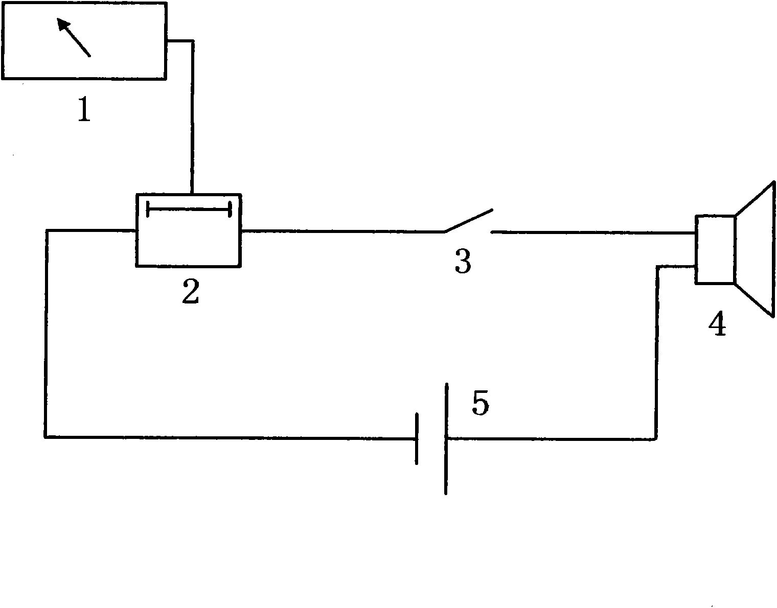
[0005] A horn controller for a motor vehicle. A delay controller 2 is installed in a horn control circuit composed of a contact 3, a horn 4 and a power supply 5. The output end of a tachometer sensor 1 is connected with the delay controller 2. The delay controller is set accordingly through the internal logic program. For example: when the speed is above 100 km / h, there is no delay control; when the speed is 80-100 km / h, that is, in the case of expressway, the delay controller is set to whistle once every 2 minutes; in the case of 40-80 km / h, the delay The time control is set to whistle once every 4 minutes; 0~40 km / h, that is, in the case of traffic jams, city centers, speed limit areas, residential areas, and factory areas, it can be set to whistle once every 5 minutes, or it can be prohibited flute. In addition, the delay controller can be connected with an external clock signal to set the time range, such as: automatically confine the horn from 24 o'clock in the middle of...


PUM


Abstract

The invention provides a device which has simple design, is convenient to mount and can effectively lessen the hooting noise of a motor vehicle. The invention adopts the following technical scheme: a delay controller is additionally mounted in a horn control circuit of the motor vehicle, and a real-time speed value of a speedmeter sensor of the motor vehicle is input into the delay controller. The invention has the advantages that unnecessary hooting noise can be greatly lessened under the condition of a traffic jam in the city center, or during the rush hour of commuting traffic, lowers the noise pollution and purifies the environment.

Description

Technical field: [0001] The invention relates to a motor vehicle horn controller. Background technique: [0002] With the rapid increase in the number of cars in my country year by year, the urban traffic situation is becoming more and more complicated. A large number of motor vehicles not only bring great pressure to urban traffic, but also bring many environmental problems, such as: exhaust pollution, noise pollution and so on. In the noise pollution of motor vehicles, the noise of car whistles has brought many adverse effects to people's life, work and study. As people's awareness of environmental protection continues to increase and the requirements for environmental quality continue to rise, preventing and controlling environmental noise pollution, protecting and improving the living environment, safeguarding human health, and promoting social harmony have become important tasks for environmental governance across the country. Pollution prevention and control regulati...

Claims


Application Information

Patent Timeline
IPC IPC(8): G10K9/12
Inventor 于涛
Owner 于涛
Learn More