Method of cooling hot forged part, apparatus therefor, and process for producing hot forged part

A cooling device and component technology, applied in heating/cooling equipment, forging/pressing/hammer devices, manufacturing tools, etc., can solve the problems of reduced machinability, energy saving, etc., and achieve good cold workability

Active Publication Date: 2009-10-28
JFE STEEL CORP
View PDF2 Cites 3 Cited by
  • Summary
  • Abstract
  • Description
  • Claims
  • Application Information

AI Technical Summary

Problems solved by technology

Therefore, in the manufacturing process of such mechanical structural members, cutting and surface grinding are indispensable. However, when the hardness of the entire member is increased, the reduction of machinability will inevitably become a major problem.
[0006] In addition, as a manufacturing facility for realizing this method, a heating facilit

Method used


Image

  • Method of cooling hot forged part, apparatus therefor, and process for producing hot forged part
  • Method of cooling hot forged part, apparatus therefor, and process for producing hot forged part
  • Method of cooling hot forged part, apparatus therefor, and process for producing hot forged part

Examples


Embodiment 1

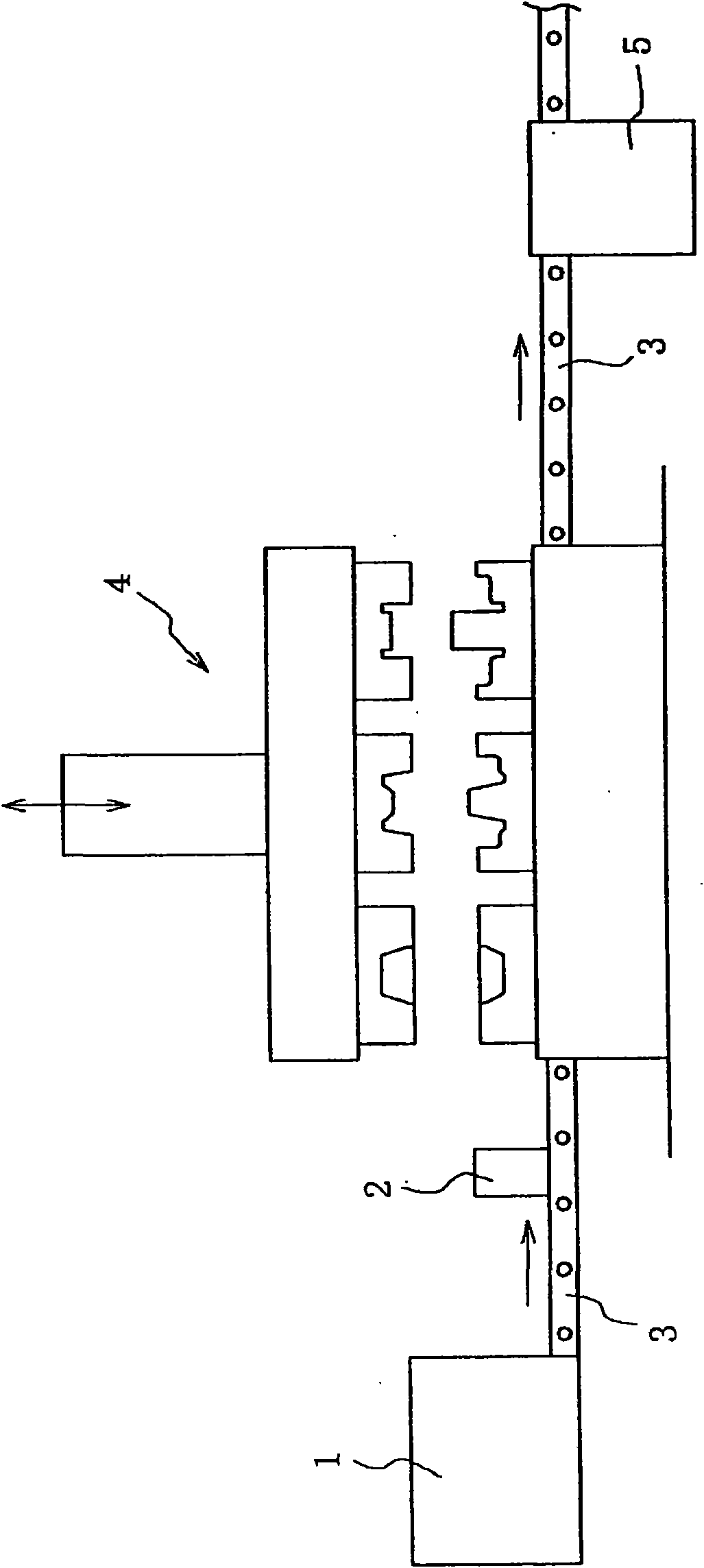
[0089] The steel with the chemical composition shown in Table 1 was melted in a vacuum melting furnace and cast into a 100 kg steel ingot. Next, the steel ingot is made into a 65mmφ bar steel by hot forging, and then imported figure 1 In the shown hot forging equipment.

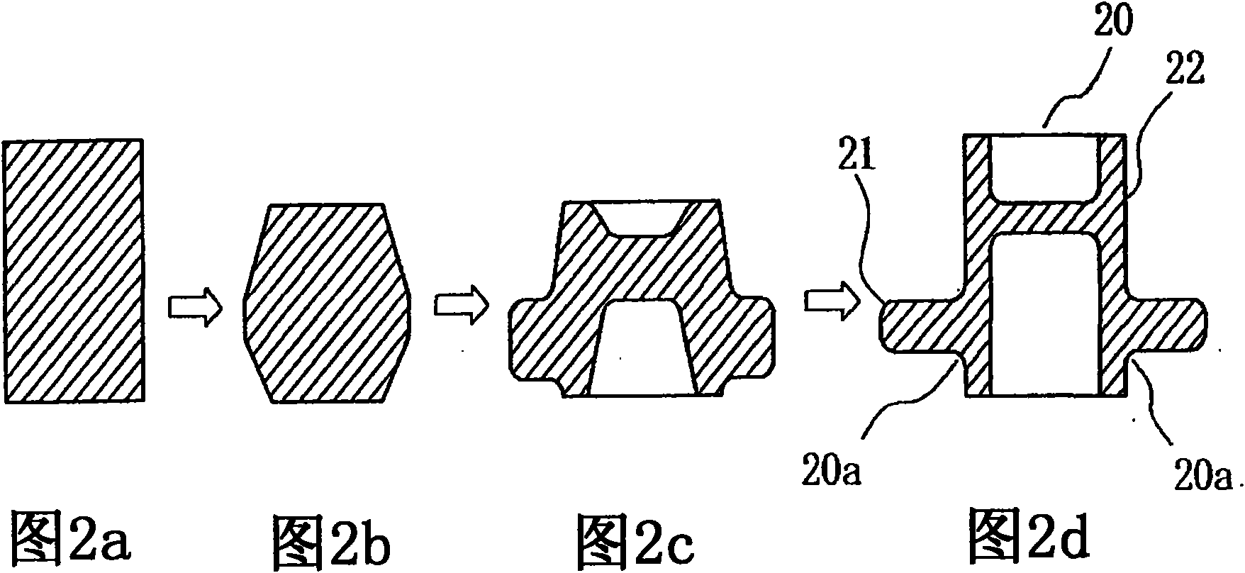
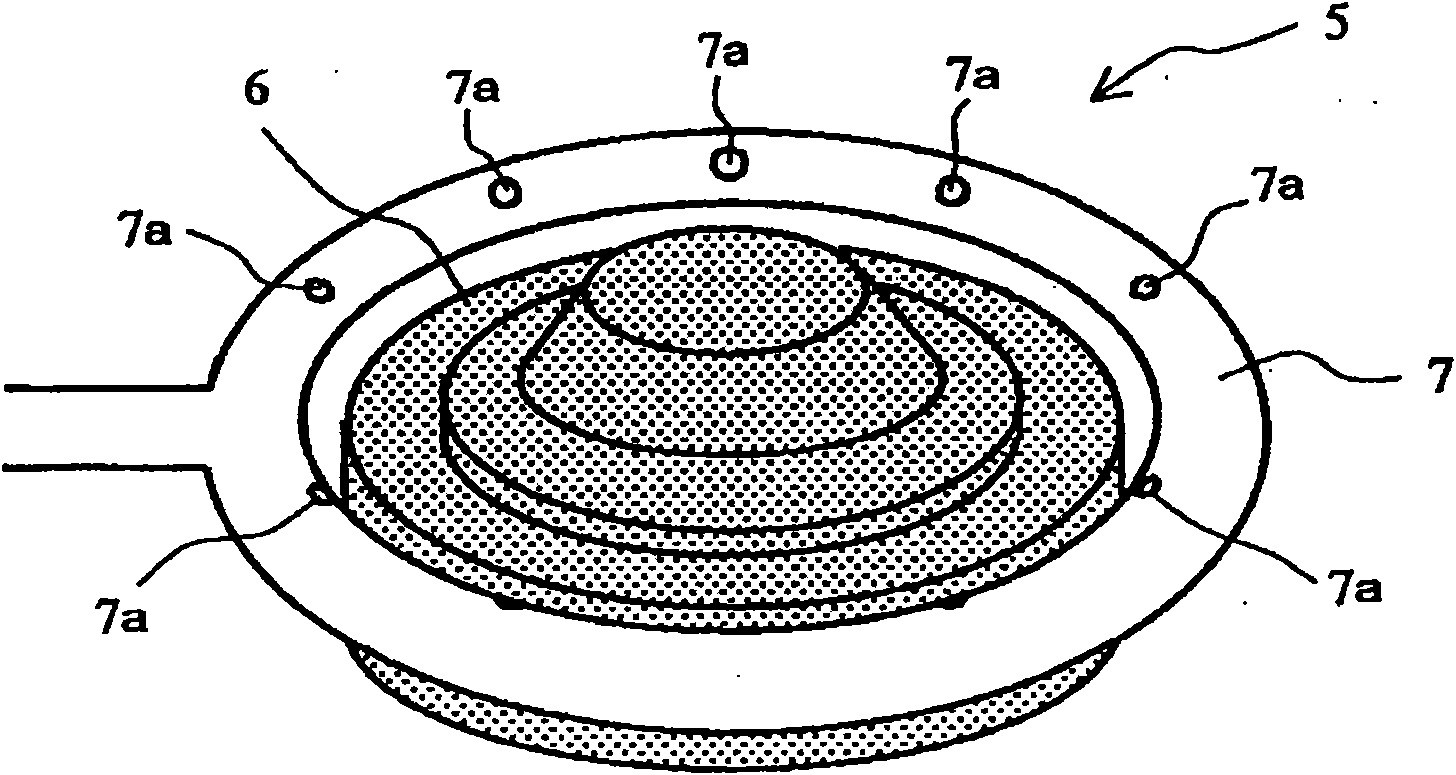
[0090] First, after heating the bar steel to 1200°C in the heating furnace 1, implement the following steps in the hot forging machine 4: Figure 2b , Figure 2c , Figure 2d shown in the three-stage hot forging, formed as Figure 2d Shown is a hot forged member 20 with a flange. The shaft diameter of the flange root of the hot forged member was 80 mm. The forged product 20 was immediately carried into a cooling device, and the flange root portion (the boundary portion between the flange portion and the shaft portion) 20a was locally partially cooled by cooling water at a flow rate of 25 l / min, and then allowed to cool. At this time, as a cooling device, Invention Example 1 used Image 6 The cooling de...


PUM


Abstract

A hot forged part is provided, wherein in production of a axial part with a flange portion by using a steel material through hot forging, good cold workability is provided to the flange portion and, in addition, high fatigue strength is provided to the boundary portion between the flange portion and the axial portion. In cooling of the hot forged part having the flange portion and the axial portion, the hot forged part is supported in such a way that the axial direction of the above-described axial portion agrees with a vertical direction during hot forging of the hot forged part or after the hot forging, and a coolant is blown locally on the boundary portion between the flange portion and the axial portion from below the above-described flange portion.

Description

technical field [0001] The present invention relates to a cooling method and apparatus for a hot forged member suitable for partial heat treatment of a forged product, and further relates to a method for manufacturing a hot forged member such as an automobile member using steel, such as a constant velocity joint, a wheel hub, etc. A typical example is a mechanical structural member represented by an engine member such as a running member and a crankshaft. Background technique [0002] Steel for machine structural use is generally produced by forming into a predetermined shape by hot forging, subhot forging, or warm forging, and then finishing by cutting. As a manufacturing process of such a member, for example, Patent Document 1 discloses a representative process of a forging production process, that is, a process in which a material is cut, heated, formed by a forging process, and heat treated as necessary. [0003] However, in recent years, in products for the above-menti...

Claims


Application Information

Patent Timeline
IPC IPC(8): C21D9/00B21K1/12B21K29/00C21D1/00
CPCB21K29/00F16C3/08F16C33/64F16C2326/02C21D9/30B21K1/12B21K1/40F16C2220/46C21D1/667C21D1/00C21D9/00
Inventor 长谷和邦木村秀途丰冈高明
Owner JFE STEEL CORP
Why Eureka
Try Eureka