Strong loop quick cooling chamber

A rapid cooling and strong circulation technology, applied in furnace cooling, lighting and heating equipment, furnace components, etc., can solve the problems of easy generation of turbulent flow, affecting the heat treatment effect of workpieces, difficult to control the gas flow in the cooling chamber, etc., to eliminate blind spots and The effect of eddy currents

Active Publication Date: 2009-11-04
SUZHOU ZHONGMENZI TECH
View PDF0 Cites 17 Cited by
  • Summary
  • Abstract
  • Description
  • Claims
  • Application Information

AI Technical Summary

Problems solved by technology

In addition, during use, it was found that because there is only one direction of blowing, the gas flow in the cooling chamber is difficult to control, and it is also easy to generate turbulent flow, and vacuum negative pressure is generated in local areas.
In this way, the outside air or the protective gas of adjacent components will flow back into the cooling chamber, thereby affecting the heat treatment effect of the workpiece.

Method used


Image

  • Strong loop quick cooling chamber
  • Strong loop quick cooling chamber
  • Strong loop quick cooling chamber

Examples


Embodiment Construction

[0016] A specific embodiment adopting the technical solution of the present invention is listed below in conjunction with the accompanying drawings.

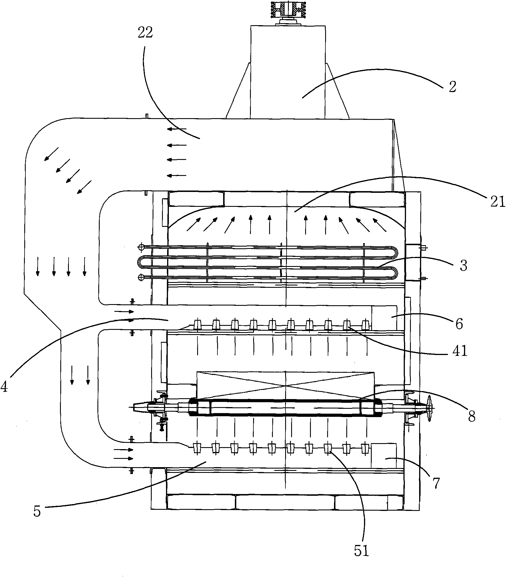
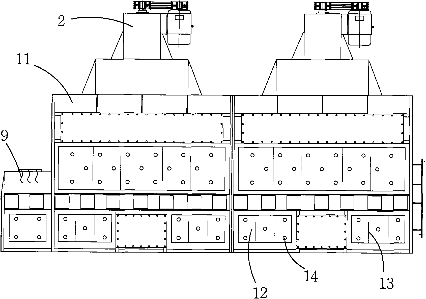
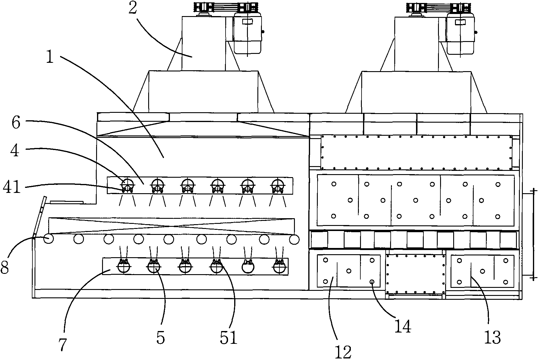
[0017] Such as Figure 1 to 3 As shown in the schematic diagram of the cooling device, the inside is an air-cooled chamber 1, a horizontal assembly line 8 runs through the air-cooled chamber 1, and the horizontal assembly line 8 carries animal feed through the air-cooled chamber 1. Inside the air-cooled chamber 1, an upper air duct assembly is provided above the horizontal assembly line 8, and a lower air duct assembly is provided below the horizontal assembly line 8. As shown in the figure, the upper air duct assembly includes six upper air ducts 4, which are arranged in parallel above the horizontal pipeline 8, and the pipe wall of each upper air duct 4 is evenly arranged along the axial direction. Several upper nozzles 41 capable of blowing downward air. The down duct assembly includes six down ducts 5, and a plurality of lower no...


PUM


Abstract

The invention relates to a strong loop quick cooling chamber, comprising a wind cooling chamber which is composed by a outer shell, a feed port and a discharge port are arranged on the both ends of the wind cooling chamber, a horizontal production line is arranged between the feed port and the discharge port, a plurality of upcast ventilation pipes and downcast ventilation pipes are arranged inside the wind cooling chamber. The upcast ventilation pipes and downcast ventilation pipes are separately arranged at the upper side and the lower side of the horizontal production line, a plurality of top nozzles which can jet air down are arranged on the upcast ventilation pipes, a plurality of lower nozzles which can jet air up are arranged on the downcast ventilation pipes, a gas circulator is arranged in the wind cooling chamber, an air inlet opening of the gas circulator is communicated with the wind cooling chamber, an air outlet opening of the gas circulator is communicated with the interior of the upcast ventilation pipes and downcast ventilation pipes, a built-in heat exchanger is arranged at the air inlet opening of the gas circulator. By arranging ventilation pipes on the upward side and lower side of the horizontal production line, strong convection can be formed by the cold air which is jeted from the nozzles of the upcast ventilation pipes and the downcast ventilation pipes and the heat on the devices can be quickly removed.

Description

Technical field [0001] The invention relates to a rapid cooling chamber, which is mainly used in the rapid cooling stations of various "continuous industrial furnaces, heat treatment furnaces" production lines, such as the rapid cooling stations of annealing and normalizing production lines, especially various Forced cooling station of "protective atmosphere heat treatment furnace". Background technique [0002] At present, in the heat treatment equipment, the cooling chamber is mostly unidirectional air cooling. Choose Party B to set the blowing pipe above and below the horizontal assembly line. The blowing pipe can only blow in one direction, and the workpiece is cooled when passing through the cooling chamber. Since this cooling is unidirectional blowing, when cooling the workpiece, only one side surface of the workpiece can be cooled. Because the other side of the workpiece faces the air outlet, it is difficult for cold air to blow there. In addition, it was discovered during...

Claims


Application Information

Patent Timeline
Patent Type & Authority Applications(China)
IPC IPC(8): F27D9/00C21D9/00C21D1/74
Inventor 蒋明根宋思科王彦荣
Owner SUZHOU ZHONGMENZI TECH
Why Eureka
Try Eureka