Phase grating displacement sensor
A grating displacement and phase grating technology, applied in instruments, optical devices, measuring devices, etc., can solve the problems of difficult adjustment, low precision, instability, etc., and achieve the effects of good signal quality, strong received signal, and simple adjustment.
- Summary
- Abstract
- Description
- Claims
- Application Information
AI Technical Summary
Problems solved by technology
Method used
Image
Examples
Embodiment 1
[0022] The phase grating displacement sensor in this embodiment includes a grating pair and a photoelectric receiving element.
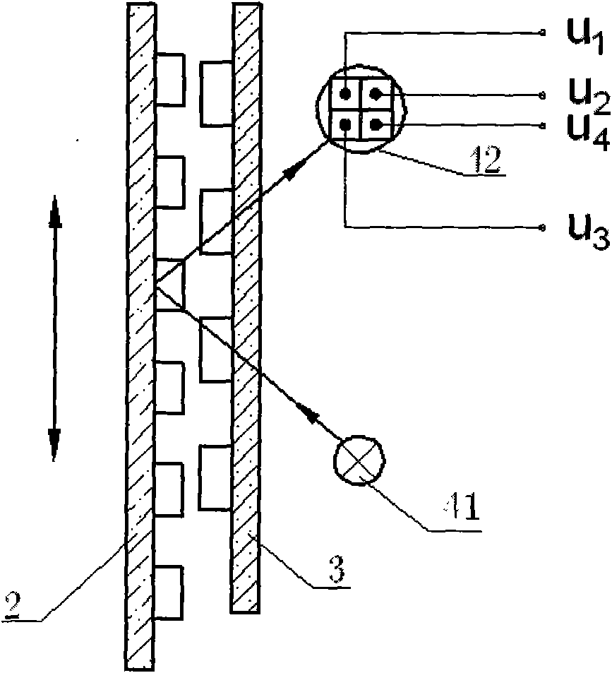
[0023] image 3 It is a schematic diagram of the principle of the grating of the phase grating displacement sensor.
[0024] Figure 4 It is the composition of the grating pair and the photoelectric replacement element in the phase grating displacement sensor.
[0025] Such as image 3 , Figure 4 The grating pair is a vernier principle grating pair, which is composed of a scale grating 2 and a reflective phase grating 3 . In the middle of the grating: the scale grating has 50 lines / mm; the reflective phase grating 3 has 49 lines / mm, and a special phase reflection film is coated on the surface of the grating. The lamination gap between the scale grating 2 and the reflective phase grating 3 is 0.03mm-0.05mm, and they are respectively fixed on the scale grating base 21 and the reflective phase grating base 31 . The scale grating seat 21 is connec...
Embodiment 2
[0028] The phase-type grating displacement sensor of this embodiment includes a grating pair, a photoelectric receiving element and a measuring rod movement system. On the basis of the first embodiment, a measuring rod moving system applying the principle of air damping is installed at the end of the measuring rod.
[0029] Figure 5 It is a cross-sectional view of the specific structure of the measuring rod movement system.
[0030] The measuring rod movement system applies the principle of air damping, including the gas cylinder 1, the piston 2 and the measuring rod 5, the measuring rod 5 and the piston 2 are sealed and connected through the joint connecting rod 4, and the piston 2 has an air chamber A and an air chamber B on the upper and lower sides; It also includes an air valve adjustment mechanism 3, which is composed of an air valve seat 31, a steel ball 32, an air hole M, and an air hole N. The air valve seat 31 is fixed in the air cylinder 1 above the air chamber A, ...
Embodiment 3
[0032] The phase grating displacement sensor of this embodiment includes a grating pair, a photoelectric receiving element and a high-magnification electronic subdivision encryption circuit. In this embodiment, on the basis of the technical solution in Embodiment 1, a high-magnification electronic subdivision encryption circuit is added; the four-phase signal output by the photoelectric receiving element is processed by the high-power electronic subdivision encryption circuit, and then converted into a representation displacement by the circuit Quantity figures are displayed.
[0033] Image 6 It is a working principle block diagram of the high-magnification electronic subdivision encryption circuit of the phase grating displacement sensor in this embodiment. The high-magnification electronic subdivision encryption circuit includes an operational amplifier circuit, a shaping circuit, an m subdivision circuit, and an n subdivision circuit. The four-phase signal output by the ...
PUM
 Abstract
Description
Claims
Application Information
 - R&D
- Intellectual Property
- Life Sciences
- Materials
- Tech Scout
- Unparalleled Data Quality
- Higher Quality Content
- 60% Fewer Hallucinations
Browse by: Latest US Patents, China's latest patents, Technical Efficacy Thesaurus, Application Domain, Technology Topic, Popular Technical Reports.
© 2025 PatSnap. All rights reserved.Legal|Privacy policy|Modern Slavery Act Transparency Statement|Sitemap|About US| Contact US: help@patsnap.com


