Methods for forming semiconductor component and gate
A semiconductor and gate technology, which is applied in the field of semiconductor devices and gate formation, can solve the problems of poor consistency of etching results, and achieve the effect of improving inconsistent etching results
- Summary
- Abstract
- Description
- Claims
- Application Information
AI Technical Summary
Problems solved by technology
Method used
Image
Examples
no. 1 example
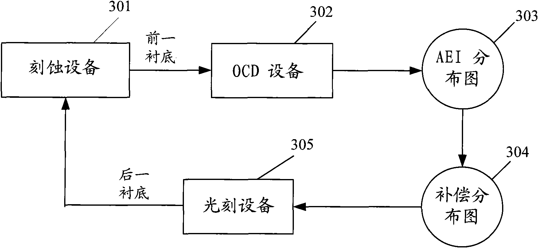
[0077] The first embodiment of the present invention introduces a method for forming a semiconductor device that uses the distribution of etching results to adjust the exposure parameters of the photolithography process. image 3 A schematic diagram illustrating the process of adjusting the photolithography process using etching result information in the first embodiment of the present invention, Figure 4 It is a flow chart of the method for forming a semiconductor device according to the first embodiment of the present invention, combined below image 3 and Figure 4 Describe in detail the specific implementation steps of the first embodiment of the present invention:
[0078] Step S401: Etching the previous substrate.
[0079] The previous substrate to be etched is sent into the etching device 301 to be etched. An etching mask pattern has been formed on the previous substrate. The etching mask pattern can be formed by photoresist directly by photolithography technology,...
no. 2 example
[0107] The second embodiment of the present invention introduces a method for forming a semiconductor device in which the distribution of etching results is used to adjust the exposure parameters of the photolithography process according to the distribution characteristics of different etching results of different etching equipment. Figure 9 It is a flow chart of the method for forming a semiconductor device according to the second embodiment of the present invention, combined below Figure 9 Describe in detail the specific implementation steps of the second embodiment of the present invention:
[0108] Step S901: using different etching equipment to process different substrates separately.
[0109] Since the size distribution of etching patterns obtained by different etching equipment may be different after etching the substrate, it is possible to use different etching equipment to process different substrates (such as experimental pieces or samples) respectively. Etching t...
no. 3 example
[0124] In the manufacturing process of semiconductor devices, the size of the gate will affect multiple performance parameters of the device, and the requirements for its size control are extremely strict. The third embodiment of the present invention introduces a method for forming a gate by using the distribution of gate etching results to adjust the exposure parameters during photolithography to improve the controllability of the gate size. Figure 10 is a flow chart of the gate formation method of the third embodiment of the present invention, Figure 11 to Figure 13 In order to illustrate the device cross-sectional view of the gate formation process in the third embodiment of the present invention, the following is combined with Figure 10 to Figure 13 The specific implementation steps of the third embodiment of the present invention are described in detail:
[0125] Step S1001: Etching the previous substrate to form a gate pattern on the previous substrate.
[0126] ...
PUM
 Abstract
Description
Claims
Application Information
 - R&D
- Intellectual Property
- Life Sciences
- Materials
- Tech Scout
- Unparalleled Data Quality
- Higher Quality Content
- 60% Fewer Hallucinations
Browse by: Latest US Patents, China's latest patents, Technical Efficacy Thesaurus, Application Domain, Technology Topic, Popular Technical Reports.
© 2025 PatSnap. All rights reserved.Legal|Privacy policy|Modern Slavery Act Transparency Statement|Sitemap|About US| Contact US: help@patsnap.com


