Method and device for flushing vapor side of high-low pressure heater in large-sized heat-engine plant

A low-pressure heater and flushing device technology, applied in chemical instruments and methods, cleaning methods using liquids, cleaning methods and utensils, etc., can solve problems affecting the safety, reliability and economy of boiler equipment, prolong unit commissioning period, Reduce equipment reliability and other issues to shorten the commissioning period, reduce unplanned outages, and improve reliability

Inactive Publication Date: 2009-11-11
ELECTRIC POWER SCI RES INST OF GUIZHOU POWER GRID CO LTD
View PDF3 Cites 6 Cited by
  • Summary
  • Abstract
  • Description
  • Claims
  • Application Information

AI Technical Summary

Problems solved by technology

Further analysis of the source of these substances is the steam extraction and heat recovery system of the high and low pressure heaters, because there are a large number of steam extraction pipes, normal drain pipes between the heaters, and heating The emergency drainage pipelines of the steam turbine and the high and low pressure heater equipment itself, these pipelines will inevitably produce machining shavings, oil, welding slag, rust and dust during the production, installation and transportation process; so that after the steam turbine starts When the high and low pressure heaters are put into the steam extraction and recovery system, these substances will be washed into the hot well of the condenser or the deaerator under the flushing of steam and water, causing the inlet of the junction water pump and the filter screen of the inlet of the boiler feed water pump to be blocked; thus It will greatly affect the safety, reliability and economy of boiler equipment; according to statistics, the total cost of starting and stopping a large thermal power unit is as high as RMB 600,000, and rust, dust, welding slag, mechanical Processed dross, engine oil, etc. cause the filter to be clogged and the number of cleanings is as high as 8 times, resulting in a large consumption of manpower and material resources, reducing the reliability of the equipment; at the same time, it also prolongs the commissioning period of the unit

Method used


Image

  • Method and device for flushing vapor side of high-low pressure heater in large-sized heat-engine plant
  • Method and device for flushing vapor side of high-low pressure heater in large-sized heat-engine plant

Examples


Embodiment 1

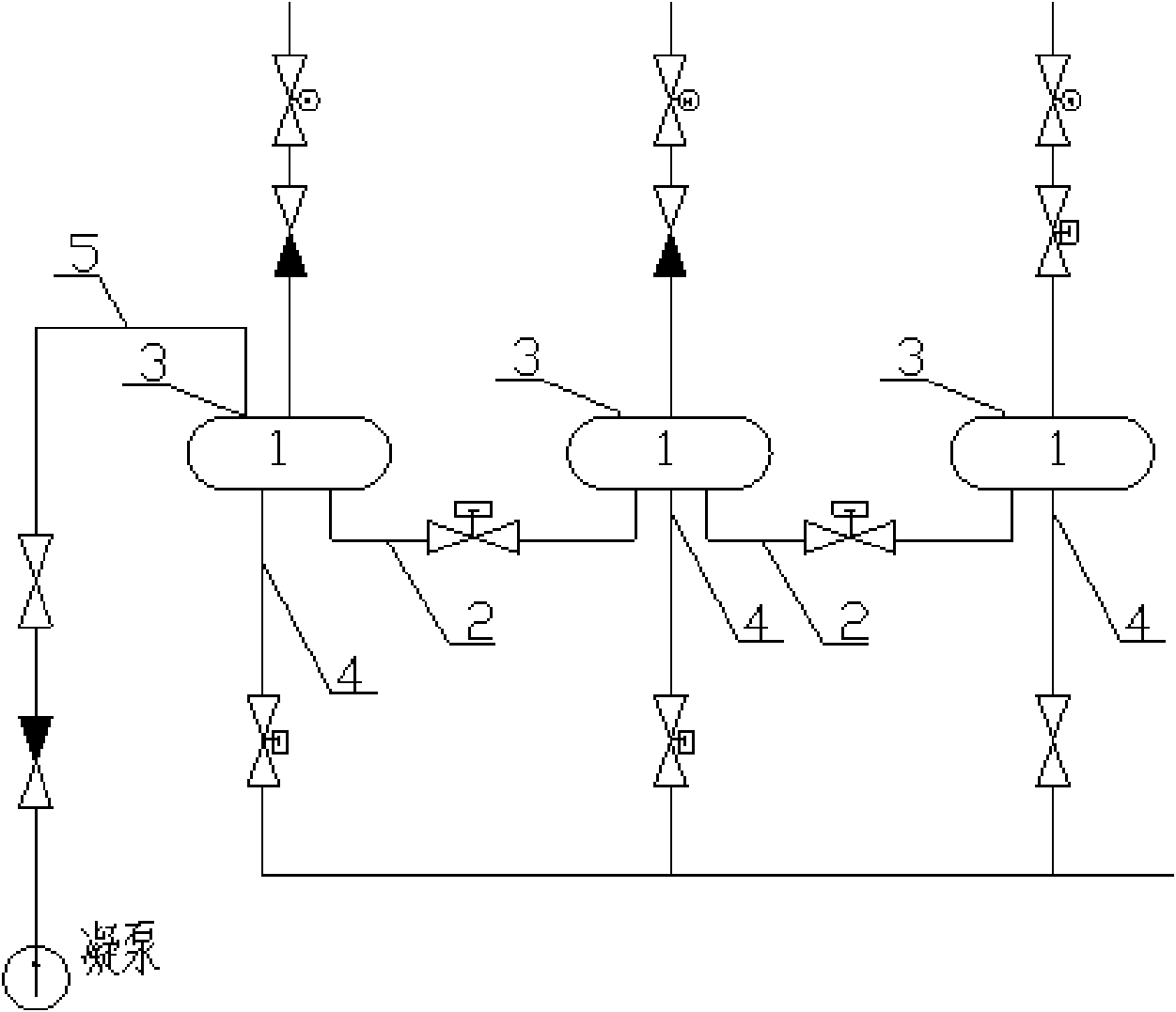
[0015] Embodiment 1: Taking three high-pressure heater systems 1 as an example, the steam side water flushing press figure 1 The steam side of more than one high-pressure heater system 1 is connected through a normal drain pipe 2 with a valve, and a safety door 3 on the steam side of one or each or each high-pressure heater system 1 is connected Water injection pipeline 5 (in this example, a water injection pipeline 5 is connected to the steam side safety door 3 of the first high-pressure heater system 1, that is, the first high-pressure heater system 1 along the drain flow direction), and the water injection pipeline 5 is connected to On the condensate pipes with valves, valves can also be installed independently on the water injection pipeline 5. When flushing, first close the steam extraction electric door, check door and drain valve in front of the steam extraction electric door of each high-pressure heater system 1 of the steam turbine. , close the valve connecting the no...


PUM


Abstract

The invention discloses a method and a device for flushing vapor side of high-low pressure heater in large-sized heat-engine plant. The valves of the normal drainage conduit and the emergency drainage conduit of a high-low pressure heater system are closed before adjusting; and water is fed into a vapor side pipe of the high-low pressure heater system through a vapor side exit; when the water pressure is close to the biggest bearable pressure of the high-low pressure heater system, the valve of the emergency drainage conduit is opened to drain water. By adopting the probability of blocking the filtering nets at the inlets of a condensate pump and a boiler water feed pump and unexpected stoppage caused by water-level accident are reduced greatly; the reliability of the equipment is improved; the debugging time is shortened; compared with other set of the same type, by adopting the technique, the filtering net blockage is greatly improved, the times for washing the filtering net at the inlet of the condensate pump are decreased by 8 times; if the expense of stopping a large-sized heat-engine set is 600,000 RMB, 4,800,000 RMB can be saved.

Description

technical field [0001] The invention relates to a method and device for flushing the steam side of high and low pressure heaters in large thermal power plants, and belongs to the technical field of high and low pressure heaters in large thermal power plants. Background technique [0002] High and low pressure heaters in thermal power plants are short for high pressure heaters and low pressure heaters. [0003] During the commissioning of large-scale thermal power plants, a major restrictive factor that plagues the start-up process of the turbine side is the blockage of the filter screens at the inlet of the condensate pump and the inlet of the boiler feed water pump. The blockage of the filter screen will cause the water outlet of the condensate pump and the feed water pump to be interrupted, resulting in difficulty in replenishing water for the boiler. In severe cases Boilers will also be forced to shut down due to lack of water. After a long-term follow-up investigation a...

Claims


Application Information

Patent Timeline
Patent Type & Authority Applications(China)
IPC IPC(8): B08B3/02
Inventor 邓彤天文贤馗冉景川王文强兰中秋
Owner ELECTRIC POWER SCI RES INST OF GUIZHOU POWER GRID CO LTD
Why Eureka
Try Eureka