Die assembly tool for extrusion molding

A technology of extrusion forming and die assembly, which is used in metal extrusion forming tools, metal extrusion dies, manufacturing tools, etc., can solve the problems of worrying about the strength of the bridge portion, interference, and hinder the smooth introduction of metal materials, so as to improve the The effect of improving pressure resistance and durability

Inactive Publication Date: 2009-11-11
SHOWA DENKO KK
View PDF4 Cites 1 Cited by
  • Summary
  • Abstract
  • Description
  • Claims
  • Application Information

AI Technical Summary

Problems solved by technology

[0008] In the conventional extrusion molding dies shown in the aforementioned Patent Documents 1 and 2, although the pressure-receiving surface of the billet is formed into a convex shape, the strength of the male die such as the pressure resistance of the metal billet can be improved to some extent. , but still worry about the strength of the bridge
Therefore, in order to sufficiently ensure the strength of the bridge-shaped portion, it is necessary to increase the thickness of the bridge-shaped portion in the male die, which leads to not only an increase in size and weight, but also an increase in cost.
[0009] In addition, in extrusion molding, especially when extruding complex shapes, it is necessary to smoothly introduce the metal material from the material introduction part of the male die to the extrusion hole in a stable state. However, In the above-mentioned conventional extrusion molding die, the metal material flowing from the material introduction part of the male die into the space between the male die and the female die is interfered by the bridge part of the male die, and the smooth introduction of the metal material is hindered, and the extruded product ( extruded products) the dimensional accuracy decreases, and it may be difficult to obtain high quality

Method used


Image

  • Die assembly tool for extrusion molding
  • Die assembly tool for extrusion molding
  • Die assembly tool for extrusion molding

Examples


Embodiment 1

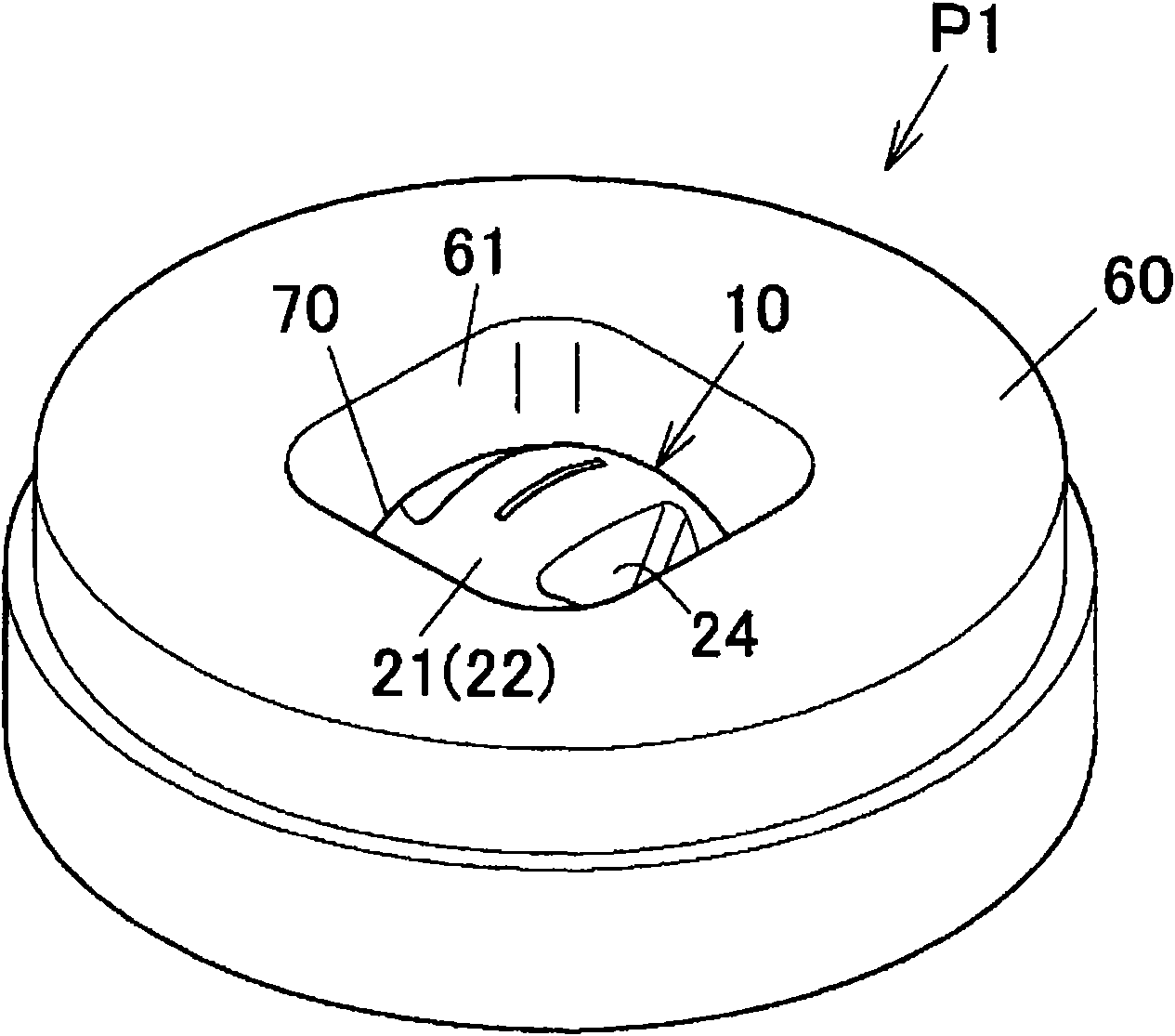
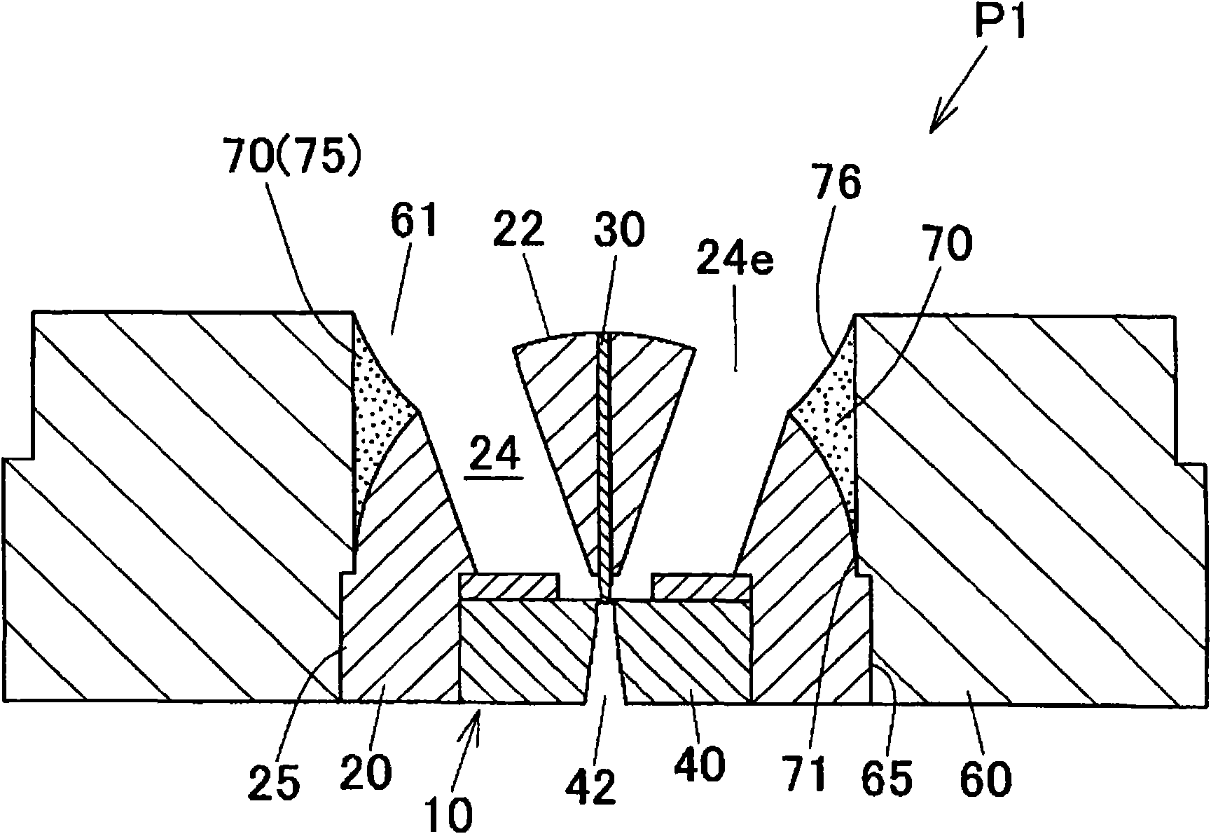
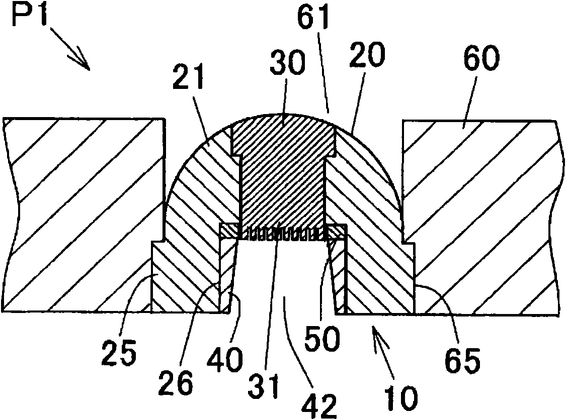
[0171] Prepare and above-mentioned embodiment (refer to Figures 1 to 4 ) corresponding to the mold assembly tool (P1). In the mold (10) of the mold assembly tool (P1), two orifices (24) of the pressure receiving part (21) are formed correspondingly on both sides of the extrusion hole (11) in the thickness direction. The inclination angle (θ) of the orifice (24) was adjusted to 20°. The blank pressure-receiving surface (22) is formed as a convex spherical surface of a 1 / 2 sphere with a radius of 30mm.

[0172] In addition, the inlet side peripheral portion of the mold installation hole (61) of the mold installation plate (60) is not specially cut off, and the inner peripheral surface of the mold installation hole (61) constitutes the peripheral wall surface of the aluminum storage portion (70) as it is. , the peripheral wall surface of the aluminum storage part (70) is arranged parallel to the axis (A1) of the mold (10).

[0173] In addition, the male mold (30) is adjusted ...

Embodiment 2

[0180] Prepare the same as the above-mentioned first modified example (refer to Figure 14 ) corresponding to the mold assembly tool (P2). In this mold assembly tool (P2), the inlet side peripheral portion of the mold installation hole (61) of the mold installation plate (60) is cut into a chamfered shape, and a cutout portion is formed on the upstream side outer periphery of the aluminum storage portion (70). (72). The inner peripheral wall surface (73) of the cutout portion (72) is formed as a tapered surface whose diameter gradually decreases toward the downstream side.

[0181] In addition, extrusion molding was performed similarly to the above, and the same evaluation was performed. The results are shown in Table 1.

Embodiment 3

[0183] Prepare the same as the above-mentioned second modified example (refer to Figure 15 ) corresponding to the mold assembly tool (P3). In this mold assembly tool (P3), the inlet side peripheral portion of the mold installation hole (61) of the mold installation plate (60) is cut into a step shape (L shape), and the upstream side outer periphery of the aluminum storage part (70) A cutout (72) is formed. The inner peripheral wall surface (73) of the cutout portion (72) is arranged parallel to the axis (A1) of the mold (10).

[0184] In addition, extrusion molding was performed similarly to the above, and the same evaluation was performed. The results are shown in Table 1.


PUM


Abstract

A die assembly tool (P1) is constructed such that an extrusion molding die (10) is placed in a die installation hole (61) of a die installation plate (60) and that a metal material introducing into the die installation hole (61) is introduced from a port hole (24) formed in a metal material pressure receiving surface (22) of the die (10). A material containing section (70) reaching the downstream side, in the extrusion direction, of the inlet position of the port hole (24) is provided outside the port hole (24).The assembly tool (P1) is adapted such that a portion (75) of the metal material introduced into the die installation hole (61) is contained in the material containing section (70).

Description

technical field [0001] The present invention relates to a die assembly tool for extrusion molding used in extrusion processing of metal materials and related technologies. Background technique [0002] Extrusion molding dies (die set) used in the manufacture of metal hollow extruded products such as aluminum heat exchange tubes in heat exchangers for vehicle air conditioners include dies with the following names: Figure 19A The interchangeable drawing die shown, Figure 19B The special-shaped hole extrusion die shown, Figure 19C Bridge pass extrusion die shown. [0003] These extrusion molds are composed of a combination of a male die (1) and a female die (2), and the core (1a) of the male die (1) corresponds to the die hole (2a) of the female die (2). Arranged in such a way that an annular extrusion hole is formed by the core (1a) and the die hole (2a). Then, the metal blank (metal material) that is extruded onto the blank pressure receiving surface (metal material pre...

Claims


Application Information

Patent Timeline
IPC IPC(8): B21C25/02
CPCB21C25/00B21C23/085
Inventor 平本公寿崎浜秀和
Owner SHOWA DENKO KK
Why Eureka
Try Eureka